10-Step Checklist for Power Meter Verification [Download Available]

INTRODUCTION:

Whether this is your first metering project or you’re a seasoned facilities manager, it’s important to remember that a little planning up front can go a long way in making your project easier.

As part of deploying a new power meter, such as the DENT ELITEpro XC, there are several tasks you will need to accomplish to ensure the meter is configured properly for your project. Before leaving the job site, it’s cruical to verify that the meter is installed properly and is recording as expected. After installation, take a few moments to follow the 10 Steps of Meter Verification.


Scroll to the bottom to download a PDF version of this list.

Step 1: Record important information about the installation for future reference.

Keep track of important installation information in one place. Use the list in the downloadable PDF (bottom of post) to jot down important details about each meter that’s installed. Key information to keep track of includes

  1. Installation date,
  2. Installer’s name
  3. Site location
  4. Meter serial number
  5. Communication setup (IP addresses & port number)
  6. Description of the load being measured.

Be sure to provide this information to any other personnel who need to access the meter for data downloads.

Step 2: Take photos.

No excuses – everybody has a cell phone in their pocket! Photos are an easy way to remember important details about the installation without having to go back to the project site. If you ever have an issue and need to contact technical support, the photos can make it simple to explain your installation. Take photos of:

  1. Outside the electrical room to aid in locating the electrical panel for the next person
  2. Inside the electrical room
  3. Of the meter installed along with the CT installation and voltage connections

Step 3: Using ELOG software, verify the logger’s Setup Table. Make sure…

  1. The correct data interval is selected (15 minutes is typical)
  2. V-high and V-low match the voltage phases the CTs are installed on
  3. CT type selection matches the CTs used
  4. CT amp selection matches the CTs used
  5. CT Phase Shift matches what’s listed in the ELITEpro XC Operator’s Guide
  6. Recorded values are selected as needed for the project

Step 4: Using ELOG software, verify the logger’s internal clock is set right.

You can verify the logger’s clock by viewing Real-Time Values and synchronizing the time to the PC or manually setting it.

When reading the logger clock or viewing data files, ELOG reads the windows settings and converts the UTC time stamps in the logger to the local time zone of the PC. If the two PCs in different time zones retrieve a data file from the logger, or read the logger clock, they will see different times.

Step 5: Check to make sure all the PhaseChek LEDs are green, which indicates all phase kW are positive and PF > 0.55

  1. If any LEDs are blue (ELITEpro XC only), the kW will be negative which is most likely caused by the CT being installed backwards.
  2. If LEDs are red, the PF is less than 0.55, which is most likely caused by the CT being placed on the wrong phase or not matching the Setup Table. It could also be caused by the load’s PF being less than 0.55.
  3. If the LED flashes red and blue, it indicates that the CT is on backwards and on the wrong voltage phase and not matching what’s listed in the Setup Table
  4. Note: If using the optional Delta 2-CT connection, it is common for an LED to be red when the system PF is <0.87 and an LED to be blue when the PF is <0.5

Step 6: Using ELOG software, view Real-Time values. Do the numbers make sense?

  1. Are the load current and watt measurements reasonable for the load?
    • Example: If the current reads are 12 Amps for a 100 HP motor, the readings are obviously too low.
    • Possible issues could be that the CTs are on the wrong wire, the CT value in the Setup Table is incorrect, or the CT type in the Setup Table is incorrect.
    • NOTE: It’s best to choose a CT in which the load will be between 10% and 100% of the CT full scale rating.
  2. Are the phase currents relatively close to each other (within about 20%) on a load that should be balanced?
    • Possible issues might include that the CTs are on the wrong wire, the CT value int he Setup Table is incorrect, or the CT type in the Setup Table is incorrect
  3. For Wye loads, are the phase watts relatively close to each other (within about 20%)?
    • Check for possible problem in phase currents were balanced: The CTs might be placed on the wrong phase, not matching the Setup Table or the CT type in the Setup Table is incorrect.
  4. Are the phase watts positive?
    • If not, it is likely that the CT is installed backwards or the wire connection at the meter is reversed. Check these conditions.
    • NOTE: It is possible when using the 2-CT method on a Delta load that one channel/phase can be negative on loads that have poor PF.
    • NOTE: Negative values could be correct for co-generation applications such a wind or solar during power generation.
  5. For WYE loads, are the phase PF readings relatively close to each other when monitoring a balanced load?
    • If not, this can be caused by the CT being placed on the wrong phase or not matching the Setup Table
  6. If available, compare to external references (within a percent or two – no two meters will read exactly the same).
    • See if the meter phase voltages match a Digital Volt Meter (DVM)
    • Check the meter phase currents with a clamp-on Amp Meter
    • Compare the meter phase watts with a clamp-on Power Meter

Step 7: Is the “Logging On” LED flashing green?

If the LED is not flashing, the meter is not recording any data! Make sure the LED is flashing prior to leaving the jobs site.

Step 8: If a remote communication method is being used (like Wi-Fi or Bluetooth), is the meter communicating?

Wi-Fi troubleshooting:

  1. Verify the Port Number in the Network Connection window in ELOG matches the meter setting
  2. The laptop Wi-Fi adapter needs to be in DHCP for use in Access Point mode (DHCP is the default setting)
  3. The ELITEpro XC IP address in Access Point mode is 192.168.1.1
  4. If a password is being used in Access Point mode, ensure the correct password is entered. If unsure, re-enter the password using ELOG
  5. If communication is lost, try:
    • Disconnecting the meter from ELOG and reconnecting
    • Disconnecting the computer Wi-Fi from the meter’s Wi-Fi

Step 9: Make sure all cabinet doors are closed and locked and all panel screws are tightened

Step 10: Ensure all trash is picked up and the site is left as clean as when you first arrived.


CONCLUSION:

Avoid the common meter installation pitfalls! Download a copy of this checklist (PDF) to take with you during your next field installation.

We would also love your feedback on this list. What do you do to ensure your meter installation is successful? Comment below with your ideas.

10 Ways the PowerScout 12 HD Solves Common Metering Challenges

INTRODUCTION:

If you’ve spent time sourcing and installing power meters, chances are you’ve run across the same challenges over and over again. Choosing the right meter, much less install it, can be tricky business. Even so, a little planning and the right power meter, can go a long way to making life easier.

We have spent years listening to customer feedback and carefully designing our latest PowerScout HD meters to ease the burden of many common problems. See how the PowerScout 12 HD can simplify your next metering project.

1. METER INSTALLATION IS PRONE TO ERRORS

The PowerScout 12 HD meter includes DENT’s patented PhaseChek feature that confirms proper CT orientation during installation. The display on the submeter shows real-time information about metered values and setup information. By reviewing real-time information on the display or connected laptop, it’s easy to double-check to ensure that metered values make sense prior to leaving the installation site. If a setting needs to be changed, the user can connect to the meter using USB or Ethernet to make adjustments in real-time, avoiding expensive and time-consuming trips back into the field.

In addition, if a CT is discovered to be on backward after the installation is complete, the direction of the CT can be reversed through a user configuration register designed for this purpose, called the “flipper.” This handy feature further eliminates special trips back into the field.

2. POWER METER CONFIGURATION IS TOO COMPLICATED

Thanks to ViewPoint HD software, the PowerScout 12 HD is easy to pre-configure before heading to the installation site. Connect the device to a PC using a USB or Ethernet cable to preset important metering parameters, such as service types, amperage ranges, communication options, and other variables. Save the setup to your computer to be used on multiple meters.

Additionally, it is now possible to configure the PowerScout 12 meter without even having it connected to your computer. Simply start ViewPoint HD software and create a configuration file to be sent to the meter at a later time. This feature is especially helpful for teams who handle configuration and installation in two separate steps.

Rather than configuring the device through a complicated push-button interface, the use of ViewPoint HD software simplifies submeter configuration. The intuitive interface allows for setup of measurement types, communications, and alarms. It also allows for seeing real-time information about the service under measurement including harmonics. Harmonics and waveform capture are also available in real-time.

ViewPoint HD software also includes a context help feature that guides users as they use the software, allowing for rapid and accurate configuration. A pop-up window with technical and Modbus register/BACnet object description information appears any time a screen object is hovered over with the mouse cursor.

3. THE INSTALLATION SITE ALWAYS HAS UNFORESEEN CHALLENGES (I.E., COMMUNICATIONS METHODS OR AMPERAGE RANGES WERE UNEXPECTED)

The PowerScout 12 HD combines popular, standard features across all models. Instead of having to choose between Modbus or BACnet, Serial or Ethernet, the PS12HD includes all these options as standard.

In addition, the PowerScout 12 HD is fully compatible with the full range of DENT current sensor options, including Rogowski (RōCoil) models. From building mains to lighting loads, mix-and-match all CT options across the meter to measure both high and low amperage loads simultaneously.

The PowerScout 12 HD may also be used on any voltage service, from 90-600VAC. The submeter is line-powered off the service under measurement.

4. THE METER NEEDS TO BE SECURE (TAMPER RESISTANT)

The PowerScout 12 HD meter has two levels of PIN protection that users can choose to assign for restricting access to submeter information. Users can be set with “read-only” or “read/write” access to the device.

Additionally, the meter may be ordered as a “no display” model, which eliminates the LCD and push buttons on the front of the device. This configuration discourages casual interaction with the meter. Interactions with “no display” versions of the meter must be made through a direct connection (USB or Ethernet) or RTU over a network.

5. I NEED TO PERFORM PREDICTIVE MAINTENANCE ON MY SYSTEM

Keep an eye on critical systems. New to the PowerScout 12 HD is the capability to set alarms on any submeter channel. Alarms may be configured to trigger by voltage and/or current over and under events. Customize the persistence setting and other parameters using ViewPoint HD.

6. I THOUGHT I NEEDED TO MEASURE X AMPS ON MY BUILDING, BUT REALIZED DURING INSTALLATION IT WAS Y AMPS

CTs may easily be swapped on the PowerScout 12 HD. The meter is not factory-configured for a particular CT type or amperage range. Instead, any DENT CT (333mV output or Rogowski coil) may be used on any submeter element. CTs may be swapped in the field with minimal effort – just use ViewPoint HD software to make adjustments to the configuration on the fly. Measure up to 4000A using Rogowski (RōCoil) CTs.

7. I NEED TO CORRELATE MY CONSUMPTION OF UTILITIES WITH ELECTRICITY

Standard on the PowerScout 12 HD are four pulse input channels which allow for the correlation of consumption of a variety of systems using standard, dry-contact pulse inputs. Configure each of the input channels independently with customizable units of measure (i.e., gallons) within ViewPoint HD software.

8. I NEED A SUBMETER THAT IS REVENUE GRADE

The PowerScout 12 HD is ANSI C12-20-2010 Class 0.2. When paired with a revenue grade current sensor, such as the DENT RoCoils or revenue grade split cores, the meter has best-in-class accuracy, ideal for any application where precision is critical.

9. I NEED TO MONITOR SEVERAL DIFFERENT LOADS IN MY PANEL SIMULTANEOUSLY, INCLUDING THE BUILDING MAINS

The PowerScout 12 HD is capable of monitoring 12 current channels simultaneously on services up to 4000A. It can monitor up to 12 single-phase or 4 three-phase loads, or a combination of single and three-phase loads (e.g., 6 single-phase loads, plus 2 three-phase loads).

10. MY METER LOST ITS CONNECTION TO THE RTU AND I NEED A RECORD OF KWH

The PowerScout 12 HD maintains an internal log of the energy data (net kWh) for each channel in the submeter that is updated every 15 minutes. This log is always active and requires no configuration. It stores 63 days’ worth of 15 minute data in its memory. The data can be retrieved by users looking to restore gaps in data collection where RTUs may have been offline or communication was interrupted. The file may be downloaded as a CSV (comma separated value) file through ViewPoint HD software. Multiple files may be combined as necessary.


CONCLUSION:

The ideal size for projects large and small, the PowerScout 12 HD is designed to monitor multiple independent loads on a single submeter. Lower installation and commissioning costs while benefiting from revenue-grade accuracy in a wide variety of large building environments including multi-tenant residential, commercial, industrial, retail, and more.

Learn how the PowerScout HD can be a valuable addition to your metering toolkit. Contact us for a quote today.

Using the Analog Channels on the ELITEpro XC to Correlate Your Consumption of Electricity to Environmental, HVAC, or Other Processes

Some features that are often overlooked on the ELITEpro XC Portable Energy Meters are the analog input channels.

Analog inputs are especially helpful when used in conjunction with power measurements to correlate the consumption of electricity with environmental, HVAC plant performance, or other process conditions. Typical uses might include logging ambient temperature, building temperatures, solar insolation, tank pressures, duct flows, etc.

The ELITEpro XC has four analog input channels that can be configured for voltage or current input in any combination among channels. The limiting specifications for anlog input are show in the table below.

Analog Input Technical Specifications
Maximum Input Voltage30 VDC, Unipolar Measurements Only.
Maximum Input Current23 maNote: the current limit will be exceeded before 30 volts of applied potential when selected for current mode or connected with reverse polarity.
A/D16 bit
Input Impedance50.0 K (voltage mode), 499 ohm (current mode)
Sampling Frequency4 HZ – per channel, 16 HZ total throughput
Accuracy<0.2% typical

COMPATIBLE SENSOR TYPES

The following sensor types are supported and selected through the ELOG software interface:

  • 0/4-20 mA externally powered current loop
  • 0-30 VDC single-ended, non-isolated

Note: The ELITEpro XC can measure input voltages up to 30.0 volts. The polarity protection circuitry, however, can only withstand 15 volts of reverse-applied polarity without permanent damage to the meter. The maximum allowable current flowing into the analog input terminal is 23 mA.

CAUTION: Ensure that the sensor current/voltage is within range and the channel is correctly configured using ELOG 15 before connecting external sensors. Sustained exposure to elevated signals may damage the ELITEpro XC and this will void your warranty.
CAUTION: Observe the correct signal polarity when connecting voltage sensors to the ELITEpro XC above 10 volts. Damaging currents may flow from the connected sensor in the event of reverse polarity or misconfiguration and this will void your warranty.

Channel types (voltage or current) should be configured using the ELOG software prior to connecting external sensors. This sequence will prevent the unexpected/unpredictable combinations of voltage transducers connected to low impedance loads (499 ohm) or current transducers with an open circuit.

The first set of Sensor and Output fields on the screen represent the Physical Range. This is where the user enters the low and high process values from the sensor. This data can typically be found on the data plate or data sheet of the sensor (typical sensor image, right). The second set of Sensor and Output fields represent the Electrical Output. This is where the user enters the minimum and maximum electrical output values of the sensor, also listed on the data plate or data sheet.

CURRENT LOOP CONNECTION

Sensors using current loops are widely used in industry to communicate analog signals in the presence of electromagnetic interference. Both 2- and 3-wire current loops (often referred to as loop powered or separately excited, respectively) are commonly used in industry. Both types of current sensors are illustrated in this section. Internally, the ELITEpro XC uses 0.1% precision 499 ohm resistors to measure the voltage drop impressed by the external current source. Current loop sensors will typically be powered from a 24-volt DC supply. The ELITEpro XC has four measurement channels. The negative terminals of each channel are common to each other and connected to the reference plane for power measurements. For this reason it is imperative that the ELITEpro XC be connected as the last component in the current loop rather than the first if multiple channels are used. Best practices are to use a single power supply for all sensors to reduce the occurrence of ground loop current between supplies.

VOLTAGE CONNECTION

Voltage output sensors and 3-wire current loops will typically use one voltage for powering the sensor and a second voltage (or current) for sending an output signal. Sometimes the power supply ground and signal reference conductor is shared between two circuits resulting in a three wire device. This economy usually comes at the installer’s expense of having to form a junction at the power supply, sensor, or meter. Sensors having four terminals are also popular and are simply connected to the meter by observing the indicated polarity between sensor and meter.

Announcing the All-New PowerScout™ HD Multi-Circuit Power Meters

48 SINGLE-PHASE/16 THREE-PHASE METERS BY INSTALLING A SINGLE DEVICE

Announcing the all-new PowerScout™ HD Series Multi-Circuit Power Meters. Designed to monitor multiple independent loads from a single meter, the PowerScout HD Series makes it easy to add many revenue-grade metering points without having to purchase, mount, wire and commission individual energy meters, resulting in lower overall installation & commissioning costs.  The PowerScout HD solution provides revenue-grade accuracy in a wide variety of large building environments including data centers, hospitals, office buildings, campuses, retail centers, and industrial complexes. The PowerScout HD Meters replace all previous-generation DENT multi-circuit meters, including the PowerScout 24.

TWO HD MODELS TO SUIT ANY INSTALLATION

One size doesn’t fit all, which is why the PowerScout HD comes in two sizes: PowerScout 12 HD has 12 circuit channels while the PowerScout 48 HD has 48 circuit channels. Both meters can be used on any combination of single- or three-phase installations and are available in a “circuit board only” or enclosure style options. Save on equipment and installation costs: the PowerScout 48 HD has a unique, two independent voltage input design, allowing it to be used on two voltage services simultaneously. The circuit board only models can often be mounted directly in the panel being monitored or in the optional enclosure and require less physical space than individual meters.

MINIMUM PART NUMBERS, MAXIMUM FEATURES

Keep it simple: Don’t fight with a long list of SKUs only to realize an important feature is missing. All PowerScout HD Series Meters are equipped with smart, standard features like the flexibility to switch between Modbus® or BACnet®, Ethernet or Serial (RS-485), or the ability to use any millivolt CT, including Rogowski coils, on any channel.  When installed, the platform agnostic PowerScout HD Series meter easily integrates within connected products of any building management system (BMS) software, models equipped with BACnet® and Modbus® protocols and can be easily utilized with any system.


Start Shopping Now

SEE HOW WE STACK UP TO THE COMPETITION

Want more information? Contact our sales team today!

Connect to a Remote ELITEpro XC Using Port Forwarding

What happens if your ELITEpro XC Portable Electric Data Logger is on a local area network at a remote project site, but you’re hundreds of miles away, at your office, and need to download data off the meter? Port Forwarding makes it possible to complete the download. And, with a little planning, you probably already have everything you need to successfully download your data.

Port forwarding is a name given to the combined technique of:

  1. Translating the address and/or port number of a packet to a new destination
  2. Possibly accepting such packets in a packet filter (firewall)
  3. Forwarding the packet according to the routing table

Port forwarding allows remote computers (for example, computers on the Internet) to connect to a specific computer or service within a private local area network (LAN). In the case of the ELITEpro XC  (or ELITEpro SP) with Ethernet, port forwarding allows remote connection between the ELITEpro XC and a computer on another network through the firewall via ELOG software.

For instance, if the ELITEpro XC is on the local area network at a remote project site, but you wish to download data off the meter from the office, you can remotely access the ELITEpro XC from any computer with an Internet connection through ELOG.

REQUIREMENTS

Prior to beginning, confirm the following information:

  1. Know the external IP address of the router on the network with the ELITEpro XC. This address is usually assigned by the ISP and is typically static. However, it may be dynamic, changing the address every other day. This can be easily found by someone inside the network by visiting www.whatsmyip.com.
  2. Confirm that your router can be configured for port forwarding. Verify this with your router’s documentation or by visiting the manufacturer’s website.
  3. Know the ELITEpro XC meter’s IP address.
Note: The ELITEpro XC itself does not need to be configured for Port Forwarding. All the configuration takes place on the router.

Each router manufacturer uses slightly different software. Check your router’s documentation for specific directions on how to port forward with your router’s software. Regardless of what software is on your router, you’ll be required to enter the same general information.

  1. A text field where you can type the name of the application or service (in this case, it’s helpful to reference the “ELITEpro XC” or the EXC’s serial number).
  2. Incoming port the router should watch for.
  3. The protocol to watch for: TCP or UDP. Choose “both” if you’re unsure.
  4. The IP address that is the destination for this port’s request (i.e., the EXC’s IP address).
  5. Which port the request should be targeted to on the destination IP. The default is 3001.

INSTRUCTIONS

Here are the steps to connecting your networked ELITEpro XC from a different network:

  1. Obtain an internal IP address that is routable to an external IP address. If you are unsure of which IP address to use, check with your IT department.
  2. The external IP address gets forwarded to the internal IP address. For instance, the external IP address 212.45.67.89 may be forwarded to internal IP address 192.168.1.50.
  3. Determine which port should e used to connect to the ELITEpro XC. The default port is 3001. Check with your IT department if you are unsure.
  4. Using ELOG on the remote PC, go through the menu: Logger > Communication > Network Connect.
  5. Enter the external IP address for the network you wish to connect to in the Network IP address box.
  6. Enter the Port Number for the logger you wish to connect to.
  7. Click OK.
  8. You should now be connected to the remote ELITEpro XC.

FOR MORE INFORMATION

You may download a PDF copy of this document to take with you into the field here.

If you need technical assistance with your ELITEpro or ELOG software, contact DENT Tech Support.

DENT Attends the CGNA Synergy Conference

Last April, DENT attended the Controls Group North America (CGNA) Synergy Conference in Savannah, GA. This conference was a meeting of the top manufacturers and distributors in the controls industry and terrific opportunity to showcase DENT PowerScout meters and accessories to other CGNA members.

Thanks to Eric Stromquist for capturing our newest PowerScout 3037 video! DENT Power Meters Rock – We could not agree more!

https://youtube.com/watch?v=3WtHd-Z3IHU%3Frel%3D0

Easy Steps to Choosing the Right Current Transformer

There’s nothing more frustrating than arriving at the project site to complete a meter installation only to realize you do not have the right current transformer in your toolkit. Not having the right tools for any job is a waste of both time and money. To avoid this, a little pre-planning goes a long way. 

Current transformers are available in a variety of styles, sizes, and amperage ranges. They vary in output and accuracy as well. With so many variables, it is sometimes difficult to choose exactly the right CT for a project. Or is it?

Whether you need assistance with choosing the right CT, or have a related inquiry, contact us at DENT Instruments.

Answer the Following Questions to Find the Right Current Transformer

Selecting the right current transformer can be as easy as answering a few questions about your project, the site, and the goals. You may be able to answer some of these questions before even setting foot on your project site. Others, such as knowing whether there is a space constraint in your electrical panel, are best answered after a site visit. Answer a few questions up front to save major headaches down the road.

QUESTION 1: WHAT TYPE OF POWER METER ARE YOU USING?

One thing to keep in mind is that just because a current transformer is compatible with a meter does not mean that it’s the best choice. For example, did you know that all DENT CTs are compatible with both ELITEpro and PowerScout series instruments? Even though they work together, a clamp-on CT isn’t the best choice to use with a PowerScout. Why? Because part of the appeal of a clamp-on CT in the first place is that it’s easy and convenient to move between panels. In fact, you’re paying more for that extra convenience. The PowerScout, along with other submeters in the industry, are designed to be permanently installed so why pay for the convenience of a clamp-on when you’re not moving it anyway?

Some ways meter choice impacts CT choice:

  1. CT inputs- is your meter designed for mV output CTs or amp output? Common industry standards are 333mV, 1A, or 5A. DENT meters are compatible with 333mV.
  2. Will the meter be installed permanently (such as with a PowerScout or other submeter) or will you be moving the meter from location to location (such as with energy audits)?
  3. Does the meter have the ability to work with flexible Rogowski coils either by themselves or with an amplifier/integrator?

QUESTION 2: HOW MANY AMPS DO YOU PLAN ON MEASURING?

Perhaps one of the most important questions to answer is how many amps will be measured. You will typically know this ahead of a site visit because it’s typically dictated by your project goals. If your goal is to measuring a lighting load in a small office, the CT required will be much smaller than if you plan on measuring a full building load for a large complex.

Keep in mind that best CT performance occurs when the current flow is between 10% and 100% of the CT full-scale value. For example, let’s say you wanted to measure four lighting circuits with #12 wires and 20A breakers. When the lights are on, the amperage measures 45 amps. The ideal CT for this example is a 50A split core current transformer.

But what about a Rogowski coil? They are easy to install and work over a broad range. Keep in mind that the best CT accuracy occurs when the load operates as close to the full rating of the CT as possible. If the load is under 20A, generally speaking a Rogowski coil is not the right choice because it is simply too big for that load. In addition, current values below 5A may cause the meter to read 0 amps.

What happens if you move your meter between many different loads? Sometimes the best solution in this case is to keep two different sets of CTs in your toolkit – one set for small loads (for example, a set of 50A split cores) and one set for larger loads, like Rogowski coils. This way, you’re covered for many different environments.

QUESTION 3: DO YOU REQUIRE A REVENUE-GRADE CT?

Thinking about your project type and goals, it’s important to keep in mind what the end-data will be used for. If you’re doing a measurement and verification (M&V) project, a standard accuracy (1% accuracy) may be accurate enough to achieve your project goals. If you are using a revenue grade meter for tenant submetering or billing purposes, every bit of accuracy counts – and a revenue grade CT would be ideal.

Examples for when to use a Standard Accuracy CT:

  1. Load studies
  2. Measurement & Verification applications

Examples for when to use a Revenue-Grade CT:

  1. Demand Metering
  2. Tenant Submetering
  3. Tenant Billing
  4. Your meter is also revenue grade

QUESTION 4: HOW LONG WILL YOUR PROJECT LAST?

Some CTs are easier to install and move around than others. Available CT styles generally include:

  • Split Core – removable leg or hinge design
  • Clamp-On – clothes-pin design, one handed operation
  • Rogowski Coil – flexible “rope-style” CT
  • Solid Core – rigid; conductor must be inserted through window

Split core, clamp-on, and Rogowski coil CTs are designed to be installed without disconnecting any wires. With the solid core, you must disconnect the conductor to feed it through the window opening of the CT. This can be an inconvenience under certain circumstances and probably not handy if you plan on moving the meter around often.

No matter which type of CT you choose, if possible, always de-energize the circuit to be monitored and follow full safety precautions outlined in your equipment manuals.

QUESTIONS 5 & 6: HOW MUCH “FREE” SPACE DO YOU HAVE IN THE PANEL? HOW BIG IS THE CONDUCTOR TO BE MEASURED?

Space constraints can be a real problem in most electrical panels. It’s possible that your meter is not the only piece of monitoring equipment installed. When multiple meters and CTs are already crammed in, extra small or flexible CTs become even more attractive. (Note: NEC does not allow equipment to exceed 75% of the electrical panel space.)

Also important to consider: What is the size of the conductor that you’ll be measuring? Is it 20 gauge wire or are you measuring around a buss bar? A split core may be ideal for a small wire, but there’s no chance that will work around a buss bar. Generally speaking, CTs with larger window openings also are designed to measure higher amps.

NEED HELP SELECTING A CT FOR YOUR PROJECT?

If you’ve read through these questions and are still unsure of which CT is best, remember that we are here to help! Contact DENT Instruments to discuss your project requirements. We will help you select equipment tailored to your project needs.

Energy & Electrical Submetering: Making the Submeter Case

Today’s escalating energy costs put increasing pressure on businesses and organizations to proactively manage their energy use. There is a growing sense of urgency to understand energy consumption patterns and to develop effective actions to manage their associated expenses.

Gaining the upper hand on electrical costs often begins with some comprehensive detective work: Taking measurements, locating energy hogs, and understanding time-of-use issues. As facility managers, engineers, and electrical supervisors know, the price of electricity is more than simply a matter of cost per kilowatt hour. Peak demand charges and power factor penalties can drive operating costs through the roof.

Load profile studies and energy audits can provide the baseline data necessary for a comprehensive energy management program. Armed with solid data, energy managers find it possible to reduce demand, contain costs, improve equipment performance, identify energy conservation measures, and curtail use during periods of high energy costs.

WHAT IS SUBMETERING?

Submetering refers to the monitoring of consumption of individual equipment within a building. In the

case of electrical submetering, the equipment being monitored may include HVAC, lighting, or kitchen/refrigeration. Utility submetering also allows a landlords or property owners to monitor consumption

in order to bill tenants for individual utility usage.

Obtaining usage and consumption data by submetering is sound business practice. Submeter benefits can include capturing lost revenues from retail, building, and department tenants, verifying cost savings on capital projects, scheduling preventative maintenance on equipment and optimizing performance of the entire facility.

BENEFITS OF SUBMETERING

  • Quickly identify whether equiment is being left on during the night or over the weekend
  • Compare usage across similar facilities, such as other branches or store locations
  • In-depth view of facility energy data in real-time
  • Identify maintenance issues before equipment failure
  • Provide facility managers with feedback on which changes are working and what to do next

Have you incorporated submetering into your energy management program? Do you rely on spot metering to compliment your submetering strategy? If you’re looking for a solid submeter solution, DENT Instruments can help. Please contact us to learn more about our PowerScout meters and flexible RoCoil (Rogowski) current transformers.

Extending the Leads on Your DENT Current Transformer

One of the most frequently asked questions in our tech support department is this: “Can I get CTs with longer leads or extend the leads myself? What’s the maximum length for CT leads?”

Standard lead length for a DENTcurrent transformer is 3 meters (with a 7 meter option available for some models). Occasionally, because of electrical room layout or other factors, there is a requirement for longer leads on a current transformer. Therefore, extending the CT leads is necessary. The following is a brief overview of options for extending CT leads based on CT type. Note that the length recommendations listed below apply to PowerScout Series and ELITEpro XC instruments ONLY. To extend RoCoil leads for use with the TCA-5, please contact Tech Support to get advice specific to your application.

For questions outside the scope of this post, please contact DENT Technical Support.

Split-Core / Hinged Split-Core Current Transformers (Including Revenue Grade Hinged Split Cores)

MAXIMUM LENGTH

Split-Core Current Transformers leads can be extended up to 500 feet using extensions of the same wire type/AWG.

WIRE TYPE

600V Rated VW-1, 105°C, 20AWG, black and white twisted pair, cURus

PURCHASING OPTIONS
  1. Purchase wire by-the-foot for DIY splicing from DENT @ $1/foot using part number WIRE 20 AWG TWPR
  2. Wire may be purchased in 1000 foot spools from Interconnect Sales with part number UL1015-20-0-9-Twist

Sure-Connect sealed butt splices from McMaster-Carr (part 9895K13) which require a crimping tool and hot air gun. Always follow manufacturer’s instructions.


RoCoil Current Transformers

MAXIMUM LENGTH

RoCoil CT leads can be extended up to 100 feet using extensions of the same wire type/AWG.

WIRE TYPE

“Bare” RoCoil: Shielded cable with thermoplastic insulation, 1000VAC VW-1, 2x26AWG, 80°C, cURus

PURCHASING OPTIONS
  1. Purchase wire by-the-foot for DIY splicing from DENT @ 1.50/foot using part number CBL ROCOIL
  2. RoCoil mV ONLY: DIY splicing is not advised for RoCoil mV CTs. Contact us for details.

Sure-Connect sealed butt splices from McMaster-Carr (part 9895K11) which require a crimping tool and hot air gun. Always follow manufacturer’s instructions.


Solid Core (Toroid) Current Transformers

MAXIMUM LENGTH

Solid Core (Toroid) CT leads can be extended up to 500 feet using extensions of the same wire type/AWG.

WIRE TYPE

UL1015 24 AWG 7 Strand Black & White Twisted Pair (1 twist per inch), 600V rated

PURCHASING OPTION

DENT does not currently stock this wire. It can be purchased by the spool (10,000 ft) through Interconnect Sales.

Sure-Connect sealed butt splices from McMaster-Carr (p/n 9895K11) which require a crimping tool and hot air gun. Always follow manufacturer’s instructions.


FOR MORE INFORMATION

To download a PDF copy of this information, click here.

If you would like to order lead wire or need more information on CT lead extensions, please do not hesitate to contact DENT Sales or Technical Support.

Glossary of Common Electrical & Power Metering Terms

The metering industry has no shortage of technical terminology and keeping it all straight is a challenge. In addition, there is terminology you might encounter on the DENT website that could use a simple definition as well, which is why we created a glossary of common electrical & power metering terminology. We hope you find this page useful.

TermDefinition
ACShort for Alternating Current, it’s an electric current which periodically reverses direction 60 times a second (60Hz), whereas direct current only flows one direction. DENT power meters are designed to measure alternating current using current transformers.
Amp HoursAn amp hour (Ah) is a unit of electric charge, having dimensions of electric current times time, equal to the charge transferred by a steady current of one amp flowing for one hour.
Ampere (amp)An ampere is a unit of measure for an electrical current; the amount of current that flows in a circuit at an electromotive force of one Volt and at a resistance of one Ohm. Abbreviated as amp. DENT power meters are designed to measure many parameters, including amps.
Amplifier/IntegratorAmplifier/Integrator circuitry is built into several DENT products, including the RōCoil mV CTs (discontinued), PowerScout Series, and ELITEpro XC meter. This circuitry, which is connected to the output of a Rogowski coil, provides an output signal that is proportional to the current. In the case of the RōCoil mV, this circuitry must be externally powered using a wall transformer (PX-XFMR).
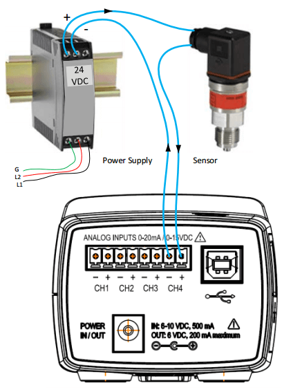
Analog Input ChannelsAnalog input channels are helpful when used in conjunction with power measurements to correlate the consumption of electricity with environmental, HVAC plant performance, or other process conditions. Typical uses might include logging ambient temperature, building temperatures, solar insolation, tank pressures, duct flows, etc. For example, the ELITEpro XC accepts 0/4-20mA externally powered current loop or 0-30VDC single ended sensors on the analog input channels.
ANSIAcronym for American National Standards Institute, which is a private, non-profit organization that oversees the development of voluntary consensus standards for products, services, processes, and systems in the United States. Several DENT products meet ANSI requirements for accuracy (i.e., the PowerScout 3037 meets the ANSI C12.20-2010 accuracy standard for revenue grade Class 0.2 performance).
Apparent Power (kVA)The product of a circuit’s voltage and current without reference to phase angle. DENT power meters are designed to measure many parameters, including apparent power.
ASHRAEAbbreviation for the American Society of Heating, Refrigeration, and Air-Conditioning Engineers. ASHRAE performs research, writes standards, and holds conferences for continuing education. DENT participates in one ASHRAE event, the AHR Expo, held in January or February each year.
AWGAWG is the abbreviation for American Wire Gauge; the standard for gauging the size of wires (electrical conductors). The cross-sectional area of each gauge is an important factor for determining its current-carrying capacity.
BACnetBACnet is a communications protocol for Building Automation and Control (BAC) Network that leverages the ASHRAE, ANSI, and ISO 16484-5 standard. BACnet was designed to allow communication of building automation and control systems for applications such as heating, ventilation, and air conditioning (HVAC) systems and their associated equipment. The DENT PowerScout Series instruments are capable of BACnet communication. See the BACnet website for more information.
Bi-Directional MeteringA meter which is capable of measuring both delivered/imported (+kW) power and received/exported (-kW) power. The term “bi-directional metering” is common in renewable applications.
CE MarkCE Mark is mandatory for certain products sold within the European Economic Area. It is similar to the FCC Declaration of Conformity used on certain electronic devices sold within the United States. A CE Mark signifies that a product meets high safety, health, and environmental protection requirements.
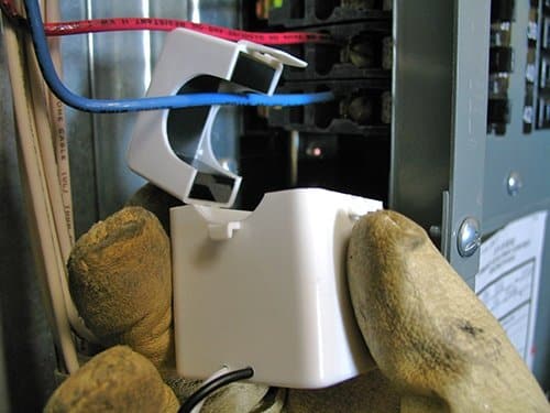
Clamp-On Current TransformerClamp-on current transformers are intended for one-handed operation during temporary energy audits. They are designed for broad utility in a compact shape. Clamp-On CTs are most often sold with ELITEpro XC instruments as their easy-to-use design makes them ideal for temporary measurement projects.
ConductorThe material through which electricity is transmitted, such as an electrical wire, transmission line, or buss bar. Current transformers are placed around a conductor to measure the flow of electricity.
ConduitA tubular material used to encase and protect one or more electrical conductors. Conduit is most often used in permanent installations with PowerScout meters.
Connected LoadAn electricity consuming apparatus connected to a generating system. Example: an electric motor.
CONTACTlogger™The CONTACTlogger, one model in the DENT SMARTlogger Series, is designed for monitoring relay closures, switches, and digital on/off signals. It comes with a 3-foot pair of wires that are connected to the switch or relay. The CONTACTlogger can be only be used on un-energized, “dry contact” devices.
Croc ClipsAlso called “alligator clips.” Croc clips are connected to the end of the voltage leads on ELITEpro XC instruments. They are used to connect the meter to voltage inside the electrical panel. Five colors are available: blue, black, red, white, and yellow (typically only used in installations outside the US).
CTAlso called “Current Transformer” or “Current Sensor.” CTs are a type of transformer that are used to measure AC current. They produce an alternating current in its secondary which is proportional to the AC current in its primary. DENT CTs are connected directly to ELITEpro XC or PowerScout power meters and are available in a variety of current ranges and styles. They are selected depending on how many amps need to be measured and physical size constraints.
CTlogger™The CTlogger, one model in the DENT SMARTlogger Series (discontinued in 2019), is designed to monitor electric load status using a clamp-on current transformer. The CT is clipped over any conductor carrying 0.25 amps AC or more. The logger is activated when there is more than 0.25 amps of current flowing through the wire to the device being monitored.
Current SensorAlso called “Current Transformer” or “CT.” Current Sensors are a type of transformer that are used to measure AC current. They produce an alternating voltage which is proportional to the AC current in its primary. DENT CTs are connected directly to ELITEpro XC or PowerScout power meters and are available in a variety of current ranges and styles, including split core, clamp on, solid core (donut or toroid), or Rogowski coil. They are selected depending on how many amps need to be measured and physical size constraints.
Current TransformerAlso called “Current Sensor” or “CT.” Current Transformers are a type of transformer that are used to measure AC current. They produce an alternating current in its secondary which is proportional to the AC current in its primary. DENT CTs have a built-in burden resistor to convert the current output of the transformer to a 333mV output and are connected directly to ELITEpro XC or PowerScout power meters and are available in a variety of current ranges and styles. They are selected depending on how many amps need to be measured and physical size constraints.
Current Transformer WindowA current transformer window is sometimes called its “opening.” The conductor you wish to measure is placed inside the window of the CT. You must ensure that the window of the CT is big enough to accommodate your conductor. Conductors can range in size from a small wire to a large busbar.
DATApro™Discontinued in 2011, the DATApro was designed to measure, store, and analyze up to 100,000 records of data from all types of sensors such as gas, water, electric, steam, HVAC, compressed air, solid or liquid waste, security, weather, or manufacturing process lines. The ELITEpro XC, with four analog input channels, is the replacement product.
DCDC, or Direct Current, is the unidirectional flow of electric card. Direct current is produced by sources such as batteries, power supplies, thermocouples, solar cells, or dynamos. The electric current flows in a constant direction, distinguishing it from alternating current (AC). “Hall Effect sensors” are sensors that can measure DC current. DENT does not carry this type of sensor.
DeltaA delta circuit is a three-phase electrical configuration where three wires are required for transmission. Delta systems are commonly used for any large motors or heaters that don’t need a neutral. Delta is also used in power transmission because it’s expensive to run a fourth neutral wire for long distances.
Demand ChargeA charge for the maximum rate at which electrical energy is used during peak hours of a billing period. Demand charges are imposed on the basis of the possible energy demand, instead of to the energy actually consumed.
ELITEpro™Discontinued in 2011, the ELITEpro Recording Poly Phase Power Meter was designed to pinpoint electric usage and quantify consumption by measuring, storing, and analyzing volts, amps, watts, volt-amps (VA), volt-amps reactive (VAR), Kilowatts (kW), kilowatt hours (kWh), kVAh, kVARh, and Power Factor. It was discontinued with the release of the ELITEpro SP power meter.
ELITEpro SP™Discontinued in 2013, the ELITEpro SP Power Meter was designed to replace the ELITEpro Recording Poly Phase Power Meter. As a direct replacement, it offered many of the same measurement capabilities, but with increased storage. In addition, the ELITEpro SP had line-power, 8MB memory, and a USB port standard. Like the ELITEpro before it, this meter was designed to pinpoint electric usage and quantify consumption by measuring, storing, and analyzing volts, amps, watts, volt-amps (VA), volt-amps reactive (VAR), Kilowatts (kW), kilowatt hours (kWh), kVAh, kVARh, and Power Factor. This model was also the first ELITEpro to allow the use of RōCoil (Rogowski) current transformers without an external amplifier/integrator. The ELITEpro SP was subsequently replaced by the ELITEpro XC.
ELITEpro XC™Introduced in 2013, the ELITEpro XC is the current-generation of ELITEpro Series meter in the marketplace. It was designed to replace the ELITEpro SP. Like the ELITEpro SP, it is designed to pinpoint electric usage and quantify consumption by measuring, storing, and analyzing volts, amps, watts, volt-amps (VA), volt-amps reactive (VAR), Kilowatts (kW), kilowatt hours (kWh), kVAh, kVARh, and Power Factor. It features 16MB memory, standard Ethernet, standard USB, and a range of communication options including Wi-Fi and Bluetooth.
ELOG SoftwareELOG Software is a Windows-based program designed to set up the ELITEpro Series meters, display metered values, and retrieve and analyze the collected data. ELOG graphically displays recorded data, performs analysis, and facilitates automatic remote data collection. ELOG is provided at no additional charge with the purchase of an ELITEpro XC and is also available as a free download on the DENT website.
Energy AuditThe process of determining energy consumption, by various techniques, of a building or facility. The goal of the audit is to identify opportunities to reduce energy consumption with the goal of saving money over time. The ELITEpro XC is commonly used to perform energy audits in commercial and industrial applications.
ETLETL is recognized as an NRTL in the United States and, in a similar capacity, as a Testing Organization and Certifying Body in Canada by the Standards Council of Canada. A product bearing the ETL Listed Mark is determined to have met the minimum requirements of prescribed safety standards and is generally considered equivalent to a UL Listed Mark. DENT split core current transformers are ETL Listed (cETLus).
FrequencyThe number of cycles through which an alternating current passes per second; in the U.S. the standard for electricity generation is 60 cycles per second (60 Hertz). DENT ELITEpro XC and PowerScout Series meters can measure at either 60Hz or 50Hz (as configured in the software).
Fused Crock ClipsSometimes referred to as “Fused Alligator Clips.” Much like the standard croc clips, fused croc clips are connected to the end of the voltage leads on ELITEpro XC instruments. They are distinguished from the regular croc clips because they include a 500mA fuse. They are used to connect the meter to voltage inside the electrical panel. Five colors are available: blue, black, red, white, and yellow (typically only used in installations outside the US).
GroundGround is a safety conductor with a low impedance path to earth. It is often called the “ground wire” or “safety ground.” It is either bare or has green insulation.
HotHot is any conductor (wire or otherwise) connected with an electrical system that has electric potential relative to electrical ground or neutral.
InverterA device that converts direct current electricity (from for example a solar photovoltaic module or array) to alternating current for use directly to operate appliances or to supply power to an electricity grid.
Kilowatt (kW)A standard unit of electrical power equal to one thousand watts, or to the energy consumption at a rate of 1000 Joules per second.
Kilowatt Hour (kWh)A unit or measure of electrical energy or consumption of 1,000 Watts over the period of one hour; equivalent to 3,412 Btu.
LegLeg typically refers to “hot leg” and is one of multiple hot conductors in an electrical system. The most common single split-phase, 240V, systems feature a neutral and two hot legs. The most common three-phase systems will have three hot legs, 208V to each other and 120V each to the neutral.
LIGHTINGlogger™The LIGHTINGlogger, one model in the DENT SMARTlogger Series, is designed to monitor the on/off status of lights. An internal photo sensor detects a nearby light source and records its status with a time and date stamp.
Line PowerLine Power is a standard feature on ELITEpro XC and PowerScout Series instruments. It allows the meter to be powered by the voltage service under measurement. Line powered instruments do not need to be connected to wall power or use a battery to operate.
LoadA load is an electricity-consuming apparatus, circuit or system (such as a refrigerator or building), connected to a generating system.
MAGlogger™The MAGlogger, one model in the DENT SMARTlogger Series (discontinued in 2019), is designed to attach to a motor housing. It contains a magnetic field sensor which can detect whether the motor is operating. It records its operating schedule with a time and date stamp.
Measurement & VerificationAlso called “M&V.” This is a term given to a process for quantifying savings delivered by an energy conservation measure, as well as the subsector of the energy industry involved in this practice. The ELITEpro XC is commonly used for M&V projects.
ModbusModbus is a serial communications protocol originally published by Modicon (now Schneider Electric) in 1979 for use with its programmable logic controllers (PLCs). Simple and robust, it has since become the de facto standard communication protocol and is now a commonly available means of connecting industrial electronic devices. DENT PowerScout Series instruments can communicate via Modbus protocol.
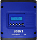
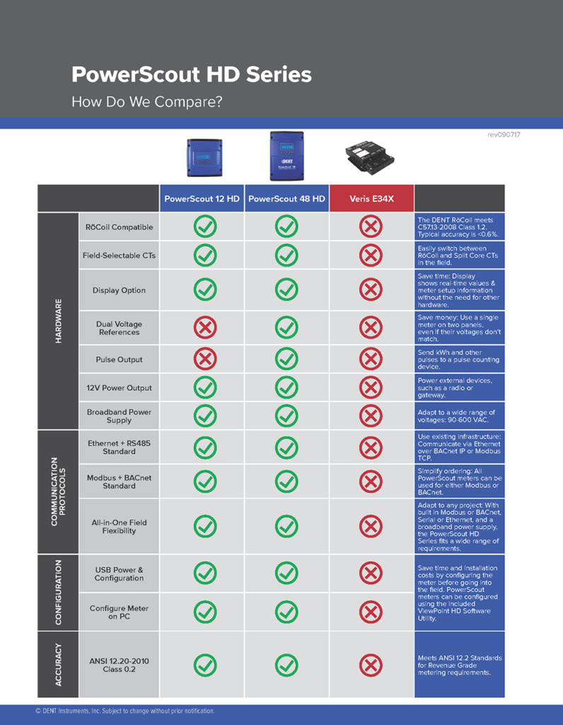
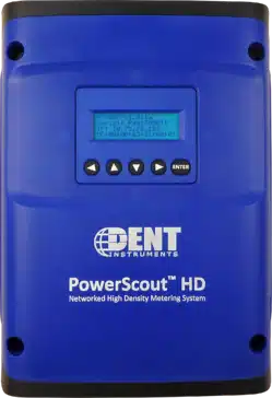
Multi-CircuitThe PowerScout HD Series meters are multi-circuit or multi-channel meters, meaning they are capable of monitoring a combination of 3-phase and/or 1-phase circuits at the same time. For example, they may be used to monitor the mains and several lighting circuits in a single electrical panel.
NECThe National Electric Code, or NEC, is a set of regulations that have contributed to making the electrical systems in the United States one of the safest in the world. The intent of the NEC is to ensure safe electrical systems are designed and installed. The National Fire Protection Association (NFPA) has sponsored the NEC since 1911. The NEC changes as technology evolves and component sophistication increases. The NEC is updated every three years. Following the NEC is required in most locations.
NEMAThe National Electrical Manufacturers Association, or NEMA, is the largest trade association of electrical equipment manufacturers in the United States. In addition to lobbying activities, NEMA publishes more than 600 standards, application guides, white papers, and technical papers. Customers often inquire about enclosures with specific “NEMA ratings,” such as 4X. DENT Instruments is a member of NEMA.
Net MeteringNet Energy = consumed energy – produced energy. Net Metering is the practice of using a single meter to measure the consumption and generation of electricity by a small generation facility (such as a house with a wind or solar photovoltaic system). The net energy produced or consumed is sold to or purchased from the power provider, respectively. Multi-circuit PowerScout meters are typically used in Net Metering applications.
NeutralNeutral wire is the return conductor of a circuit. United States electrical codes require that the neutral is neither switched nor fused and that it be connected to earth at the service panel only and at no other point in the building wiring system.
PhaseChek™PhaseChek™ is a patented technology (Patent No. 7,612,552) which allows a user to see when the current sensors on the meter have been improperly wired or connected. This greatly reduces set-up time and helps to eliminate installation errors. PhaseChek is available on ELITEpro XC and PowerScout Series instruments.
Port ForwardingPort forwarding allows remote computers (for example, computers on the Internet) to connect to a specific computer or service within a private local area network (LAN). In the case of the ELITEpro XC with Ethernet, port forwarding allows remote connection between the ELITEpro XC and a computer on another network through the firewall via ELOG software.
Power FactorIn electrical engineering, the power factor of an AC electrical power system is defined as the ratio of the real power flowing to the load to the apparent power in the circuit and is a dimensionless number in the closed interval of -1 to 1. A power factor of less than one means that the voltage and current waveforms are not in phase, reducing the wattage of the load. Power factor (aPF and dPF) is captured by the ELITEpro XC and PowerScout Series instruments.
PowerScout SeriesPowerScout is the trade name given to the DENT Instruments line of submetering instruments. PowerScouts are typically installed permanently in electrical panels to give ongoing information about energy consumption. They are available in single-circuit (PowerScout 3037) and multi-circuit (PowerScout HD Series) versions.
Pulse InputPulse inputs are available on the PowerScout 24 and are used to count, accumulate, and scale pulses received from non-DENT external pulse initiating meters such as gas, water, or other electrical meters.
Pulse OutputPulse outputs are available on PowerScout Series meters and are used to send kWh or other pulses to a pulse counting device, such as a data logger.
Revenue GradeRevenue grade meters and current transformers meet rigorous testing and accuracy requirements. Typically, they meet ANSI C12.20-2010 Class requirements of better than 1% accuracy (see PowerScout Series). The term “revenue grade” in general use can mean different things to different organizations. It’s possible to have a meter meet the Class 0.2 accuracy requirements, but unless it’s paired with an equally accurate or better CT, the end result may or may not be considered “revenue grade.”
RMS (Root Mean Square)For a cyclically alternating electric current, RMS is equal to the value of the direct current that would produce the same average power dissipation in a resistive load. DENT ELITEpro XC and PowerScout meters offer true RMS measurements using high-speed digital signal processing (DSP).
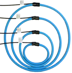
RoCoil™RōCoil is the DENT trade name for our line of Rogowski Coil current sensors. RōCoils are known for their installer friendly features such as large window size, light weight, wide current range, and mechanical flexibility for mounting in tight quarters. RōCoils can be used with both ELITEpro XC and PowerScout instruments.
RoCoil™ mVRōCoil mV, discontinued in 2019, is the DENT trade name for our line of Rogowski Coil current sensors that include amplifier/integrator circuitry on the lead wire. This circuitry allows these CTs to be used on meters which do not have amplifier/integrator circuitry build in (such as the legacy ELITEpro meter). This circuitry means that the RōCoil mV requires external power, usually provided by a wall adapter (PX-XFMR).
RoCoil™ TCA-5Discontinued in 2019, the RōCoil TCA-5 is a three-channel integrating transconductance amplifier (TCA) that converts the 131mV/1000A electrical output signal from the RōCoil sensor to a 5 amp AC current, emulating a traditional current sensing transformer. The RōCoil TCA-5 is designed to make RōCoil CTs compatible with 5 amp current input power meters.
Rogowski Coil Current SensorRogowski coil, named after Walter Rogowski, is an electrical device for measuring alternating current (AC) or high-speed current pulses. It consists of a helical coil of wire with the lead from one end returning through the center of the coil to the other end so that both terminals are at the same end of the coil. The coil is then wrapped around the conductor whose current is to be measured. RōCoil is the trade name given to the DENT line of Rogowski coil CTs.
RS-485RS-485 is a standard defining the electrical characteristics of drivers and receivers for use in serial communications systems. PowerScout instruments are capable of communicating via Modbus or BACnet over RS-485 networks.
Setup TableELITEpro Series instruments require that they be configured for use by first creating a Setup Table file in ELOG software and then loading the file into the meter. The Setup Table file will tell the meter what current sensors, recording interval, and service type it will be monitoring.
Shark ClipsShark clips for the ELITEpro Series can be used in place of the standard Croc Clips in applications where Croc Clips may not physically fit. They are designed for narrow installations and are rated for 600V.
Single PhaseSingle phase power is the distribution of alternating current (AC) electric power using a system in which all the voltages of the supply are either in phase or out of phase by one half a cycle (180˚). Single phase distribution is used when loads are mostly lighting and heating, and electric motors are small (5HP and under) (such as found in most US residential homes). DENT ELITEpro Series and PowerScout Series are designed to measure on single phase as well as three phase systems.
SMARTlogger™The SMARTlogger Time-of-Use data loggers are designed to monitor the on/off status and total time-of-use data of power consuming devices such as lights, motors, switches, or other electric load generating at least 0.25 amps. There are four models of SMARTloggers available: LIGHTINGlogger, MAGlogger, CTlogger, and CONTACTlogger. SMARTloggers are battery powered and record up to 32,000 records (on/off transitions) in internal memory. SMARTware software is used to configure the logger and download and analyze the data.
SMARTware™ SoftwareSMARTware is an easy-to-use Windows-based software application for use with DENT SMARTlogger Time-of-Use loggers. It can be used to download and analyze data from SMARTlogger instruments, configure the logger clock, and export recorded data as a CSV file to Excel.
Split Core Current TransformerSplit Core current transformers are an economical CT choice. Like other CTs, they provide a linear output voltage that is directly proportional to the input current. They are safely and easily installed over existing electrical power lines without disconnecting lines. They produce 333mV at full scale and are available for loads up to 1200A. They are compatible with ELITEpro Series and PowerScout Series instruments.
SubmeterSubmetering refers to the monitoring of the electrical consumption of individual equipment within a building, such as HVAC, lighting, refrigeration, kitchen equipment, etc. In addition to the “main load” meter used by utilities to determine overall building consumption, submetering utilizes individual “submeters” that allow building and facility managers to have visibility into the energy use and performance of their equipment, creating opportunities for energy and capital expenditure savings. PowerScout Series instruments are typically used for building submetering projects.
Test & MeasurementAt DENT, Test & Measurement refers to a category of products designed for Measurement & Verification (M&V) studies, electrical load profiling, energy audits, and new technology assessment. DENT Test & Measurement products include the ELITEpro Series meters and SMARTlogger instruments.
Three-Phase SystemsThree-phase electrical power systems have at least three conductors carrying alternating current voltages that are offset in time by one-third of the period (120˚). A three-phase system may be arranged in a delta (Δ) or wye. DENT ELITEpro Series and PowerScout Series instruments are designed to monitor both single and three-phase power systems.
Time of Use (TOU)Time-of-Use is the time a particular load is turned on. For example, how long, and at what time the lights have been on in a particular room. Time-of-Use data can be collected using the DENT SMARTloggers (sometimes called DENT TOU loggers).
Toroidal Solid Core CTsToroidal Solid Core CTs are transformers which use magnetic cores with a toroidal (ring or donut) shape. They consist of a circular ring or donut shaped magnetic core of ferromagnetic material, such as a laminated iron or ferrite, around which wire is wound. Because the core is solid (as opposed to a Split Core), they require the existing electrical power lines to be removed for installation. Therefore, they are generally used in new building installations to minimize disruptions. The DENT RGT Series are toroidal current transformers which are designed for Revenue Grade IEEE Class metering applications. They are compatible with both ELITEpro Series and PowerScout Series meters.
Twisted PairTwisted pair is a type of wiring in which two conductors of a single circuit are twisted together for the purposes of cancelling out electromagnetic interference (EMI) from external sources. This type of wiring is used on several DENT current transformers, including split core CTs.
ULUL (Underwriters Laboratory) is an American safety consulting and certification company. They provide safety-related certification, validation, testing, inspection, auditing, advising, and training services to a wide range of clients, including manufacturers. UL is a Nationally Recognized Testing Laboratory (NRTL). Several DENT instruments and CTs are UL Listed (cULus), including the ELITEpro XC, and PowerScout 3037, or Recognized (cRUus), including the board-only versions of the PowerScout HD meters.
VFDAcronym for Variable Frequency Drive. A VFD is a type of adjustable speed drive used in electro-mechanical drive systems to control AC motor speed and torque by varying motor input frequency and voltage. DENT power meters are capable of measuring the input side of the VFD, but not the output side, as the frequency is not set at either 60 or 50 Hz and the voltage may not be a sinusoidal waveform.
ViewPoint™ SoftwareViewPoint is a software utility which allows for easy configuration of the PowerScout meter. It allows a user to switch between communications protocols (Modbus or BACnet), check real time metered values, read & write registers, update the scalar values, and select current transformers. It is provided at no additional charge with the purchase of a PowerScout meter and is also available on the DENT website as a free download.
WyeA Wye is a three-phase voltage system with the three phases connected to a single neutral point (star). This allows the use of two different voltages from all three phases, such as a 277/480V system, which provides 277V between the neutral and any one of the phases and 480V across any two phases.

Information in this document compiled from Wikipedia, energy.gov, and DENTinstruments.com

https://en.wikipedia.org/wiki/Main_Page

https://energy.gov/eere/energybasics/articles/glossary-energy-related-terms

Haul Out the Holly | DENT Instruments

HOLIDAY DECORATING CONTEST AT DENT!

We are really getting into the holiday spirit here at DENT this year! Each department is participating in a friendly, little holiday decorating competition. The rules are simple: Each department is given $50 to decorate their space. Decorating items can also be brought from home. Which department’s decor will reign supreme?


ENGINEERING

Engineering opted for a homey, living room theme, complete with a life-sized fireplace and real pine tree. The theme incorporated many DENT products, including the new PowerScout 48 HD with custom “Merry Christmas” edition firmware. Nice touch, team!


PRODUCTION

Production’s theme is “Santa’s Workshop,” which is completely appropriate because their department is where the elves build each and every DENT product. The department is furnished with present storage and detailed Santa route planning maps and a cozy fireplace as well. Santa himself made an appearance as well!


ACCOUNTING/ADMINISTRATION

Our accounting team decorated their space with festive holiday-themed wrapping paper to completely change the look of the office! Nice wrapping job, ladies!


SALES & MARKETING

Peppermint was the theme for Sales & Marketing, with dozens of hand-made peppermint “candies” hanging from the ceiling. Red and white everywhere, the room even smelled like peppermint!


From all of us at DENT Instruments, we hope you have a safe and happy holiday season!!

PS: The Production Department’s decorations won this year’s competition – their dedication to wearing elf outfits all day put them over the top! Congrats to Production!!

How to Update the Firmware on the ELITEpro XC Power Meter

Firmware is software that is used as the control program for the microprocessor in your ELITEpro XC power meter. Firmware updates provide new features and bug fixes for the meter and can be field-installed on the ELITEpro XC (as opposed to needing to come back to the factory for an upgrade). Here’s how you can make sure your firmware is update-to-date & perform an update if needed.

New firmware files are generally bundled with updated ELOG software. Recent versions of ELOG check for software updates automatically. New software and firmware can be downloaded at no charge from the DENT website on the Software Download Page.

You can check the firmware version of your ELITEpro XC from the Tools menu in ELOG software. Select Tools > Update Logger Firmware. The Firmware Update dialog box displays. No update is required if your Firmware File version and the Logger Version are the same.


DOWNLOADING AND INSTALLING FIRMWARE

To install firmware updates, first make sure that your logger is connected via USB cable. Then:

Step 1: Select Tools > Update Logger Firmware.

The following dialog box displays:

Step 2: If necessary, click the Browse button to locate the firmware update file.

Step 3: Click Update

Step 4: The Update Progress bar displays the progress of the firmware update.


If you’re having trouble updating the firmware for your logger, please contact DENT Tech Support for assistance.

ISO 9001:2015 Certification

Months of hard work and preparation have paid off and we are proud to announce that DENT has successfully transitioned to the new ISO standard and is now accredited with ISO 9001:2015 certification! The Company was previously certified to the ISO 9001:2008 standard.

Crafting instruments of superior quality is serious business. Each of our products is manufactured in observance of the highest quality standards. Products that do not match our standard do not make it through the process. It’s that simple.

Each department within DENT was independently audited to ensure our compliance with the new standard.

Through our quality policy, DENT Instruments will focus on quality, customer satisfaction, and continuous improvement in everything we do.

Our quality management system ensures that we:

  • Meet or exceed the requirements and expectations of our customers
  • Continuously monitor, measure, and improve customer satisfaction
  • Continuously monitor, measure, and improve our own performance

Obtaining customer feedback is extremely important to us, which is why we want to hear from YOU! Send us feedback here.

For more further information on our ISO certification or procedures, please contact us.

Join Us at the New Jersey Electrical Connections Trade Show

DENT Instruments will be exhibiting at the upcoming New Jersey Elecrical Connections Trade Show this November 10th, to be held at the Marriott in Saddle Brook, NJ.

The event features a FREE 2-hour CEU course from 10:00am-noon presented by David Bovankovich, a 30+ year expert in the electrical industry. The presentation will cover submetering, energy management and power quality and is FREE to licensed electricians and students!  We have limited space available for this course, so be sure to register as soon as possible to reserve your spot!

In addition to the CEU course, the afternoon event will be a tabletop showcase show featuring 30+ electrical manufacturers, associations and distributors that support electrical contractors in the state of New Jersey.  We are excited to help educate contractors and students on new electrical products, industry updates, distributor promotions as well as introduce local and partner associations that also support New Jersey’s 15,000 strong base of electrical contracting professionals.

Attend the show for FREE – Click Here.

Maximize Power Meter Performance with New Revenue Grade Current Transformers from DENT Instruments

New Revenue Grade Current Transformers (0.2% accuracy) are now available from DENT Instruments. These split-core and toroidal CTs are designed for applications which require maximum accuracy & precision. The superior performance and robust design make them ideal for field installation in applications such as energy & demand metering, tenant submetering, and load surveys.

Maximize end-to-end accuracy by pairing these CTs with a revenue grade power meter, such as the DENT PowerScout 3037 or PowerScout 24.

Hinged Split Cores

DENT’s SRS & SRL Series hinged split-core current transformers are designed for Revenue Grade
applications that require maximum accuracy and precision. The superior performance, robust design, and unique shrouded snap, lock & tilt top of the SRS/SRL Series CTs make them ideal for field installation in high accuracy current measurement applications such as energy and demand metering, tenant submetering and load surveys. Revenue Grade performance of these CTs meets or exceeds IEC 61869-2 Class 0.2; IEC 60044-1 Class 0.3; and IEEE C57.13 Class 0.3.

Toroidal Solid Core

DENT’s RGT Series toroidal current transformers are designed for Revenue Grade applications that require maximum accuracy and precision. The superior performance, robust design, and compact size of the RGT Series CTs make them ideal to be used for current measurement in panelboards, switchgear, and industrial control equipment. Revenue Grade performance of these CTs meets or exceeds IEC 61869-2 Class 0.2; IEC 60044-1 Class 0.3; and IEEE C57.13 Class 0.3.

Learn about the full range of DENT Current Transformers here or request a quote.

Case Study: Using the ELITEpro Power Meter to Measure Energy Savings

I belong to a church where we recently did a major lighting upgrade.  Old fluorescent and incandescent lights were replaced with LED lighting.  It was a great opportunity to use the DENT ELITEpro XC Portable Power Meter and RoCoil current transformers to monitor power consumption before and after the upgrade.  In case you are not familiar with the ELITEpro, it is a portable poly-phase power recorder.  Powered by the input voltage connection, it has available current transformers from 5A to 5000A full scale, and enough memory for years of recording.

The church has a 3-phase 240V delta service.  The ELITEpro Power Meter and RoCoil current transformers were connected at the main service entrance and programmed to record every 15 minutes for exactly 1 week, Midnight Friday to Friday.  Note that its sampling rate is 1/second, so the measured values have revenue grade accuracy.

The initial measurement were taken in late March of 2015.  Power consumption was 2981 KWH, the peak demand was 54 KW.

Lighting was upgraded in several stages, the last being completed in late October 2015.  A follow up recording was done for exactly the same time frame during the last week of October.  Power consumption was down to 1588 KW with a peak demand of 21 kW, a reduction of 48%.   Based on the electric rate, this upgrade should save around $7,000 per year.

The DENT ELITEpro Power Meter is an excellent, cost effective tool for measuring and documenting energy consumption.  In addition to what we’ve done here, other common applications include:

  • Energy audits on branch circuits or individual loads.
  • Documenting savings associates with lighting, motor, compressor, or other upgrades
  • Documenting savings associated with compressed air leak audits/repairs
  • Support for energy savings rebate filings
  • Load profiling
  • Sizing studies for backup generators or UPS’s
  • Green energy studies – it can record bi-directionally for solar/wind net metering.

Learn more about the ELITEpro XC Power Meter.

About I&E Central: I&E Central is an authorized DENT Instruments Distributor founded by Bob Dunn in 2001 and is based near Rochester, NY. I&E Central has grown over the past 13 years, expanding its portfolio and technological expertise in that time.  We currently maintain a physical presence in Ohio, Pennsylvania and New York, but I&E proudly supports customers throughout the US. Contact I&E Central here.

Measuring DC Loads with an ELITEpro XC

The ELITEpro XC current input channels can accept +/-1VDC. The ELITEpro XC Portable Power Data Loggers analog channels can accept any sensor that has a 0-10 V or 0-20 mA or 4-20 mA signal. What does this mean for DC measurements? Non-DENT sensors may be used on the current and/or analog inputs to measure DC loads. Note that when the DC transducer is connected to the ELITEpro XC CT input, DC power will be reported as long as the DC voltage is connected to the voltage inputs. When the DC transducer is connected to the analog inputs, DC power will not be reported.

Below are two options for measuring DC loads with an ELITEpro XC instrument.


USING THE AEMC MR521 AC/DC CURRENT PROBE

The AEMC MR521 can be used either on the CT inputs or the analog inputs.

USING THE MR521 ON THE CT INPUTS

When using the AEMC MR521 on the ELITEpro XC CT inputs, you may select from two amperage ranges: 100A or 1000A.

  1. 150A:10 mV/A range = 100 Amps DC max
  2. 1500:1 mV/A range = 1000 Amps DC Max

USING THE MR521 ON THE ANALOG INPUTS

If the CT is used on the analog inputs, the full 150A or 1500A range can be used.

OTHER INFORMATION

Note that the AEMC MR521 has a 50 hour battery life and a 2-5% accuracy. List price is $389 (cannot be ordered from DENT). Also keep in mind that a minimum of 80VDC is needed to power the ELITEpro XC.


USING THE NK TECHNOLOGIES DT SERIES DC CURRENT TRANSDUCERS

The NK DT Series current transducers can be used on DC currents from 0-50A or 0-100A depending on the NK DT model chosen. The NK DT Series have 3 available output ranges that must be chosen at the time of purchase.

USING THE NK DT ON THE CT INPUTS

If you wish to use the NK DT on the ELITEpro XC CT inputs, select an NK DT model with 333mV out.

USING THE NK DTON THE ANALOG INPUTS

If you wish to use the NK DT on the ELITEpro XC analog inputs, select an NK DT model with 10VDC output.

POWER SUPPLY OPTIONS

The NK DT Series current transducer has two power supply options. If you plan on using the CT with the ELITEpro XC’s CT input channels and power the NK DT transducer via the ELITEpro XC’s 6VDC power out, choose the 5VDC power supply option. Cannot be ordered from DENT.


FOR MORE INFORMATION

For questions outside the scope of this document, please contact DENT Technical Support at: support@dentinstruments.com / 541-388-4774.

Metering Application: Integrating the ELITEpro XC Meter with a Cellular Communication Module for Remote Metering

By Francisco Sotela, Director of Iotech

OBJECTIVE

The objective of this solution is to manage the ELITEpro XC Power Meter from the office without having to perform a site visit to collect the metered data, increasing efficiency and reducing project costs. Learn how the ELITEpro XC was integrated in the ideal remote solution.

DESCRIPTION OF APPLICATION

The power company in Costa Rica has customers throughout the country, many located in remote areas. Often, the power company needs to perform a temporary study (energy audit) with a customer who reports electrical problems, such as excessive consumption or short circuits. The audits are performed using an ELITEpro XC power meter at the customer site.

Because of the distances involved, it was important to develop a remote communication solution for the ELITEpro XC meter. Although the ELITEpro XC can be purchased with a Wi-Fi option, wireless internet is not always available at the customer site. Therefore, it was determined that cellular communications would be required.

Iotech, DENT’s Authorized Distributor in Central America, developed a solution where the ELITEpro XC was integrated with a cellular router in a weatherproof control cabinet. The ELITEpro XC meter was connected to the cellular router via the Ethernet port, allowing the auditors to connect to the ELITEpro XC meter from anywhere in the world using the Internet. Metered values, as well as harmonics, could be viewed in real-time using this solution.

The control cabinet used was weatherproof and could withstand direct sunlight – adding an effective layer of protection to the ELITEpro XC and cellular router. Cables for voltages and current sensors traveled through separate conduits in the side of the cabinet. The cellular communication module was powered by an extension that traveled through the side of the cabinet.

This solution has benefited the power company by saving countless trips into the field to gather data from the energy meters. It has also allowed the engineers in charge of the audit to verify meter setup prior to the installer leaving the field, ensuring proper configuration and reducing the number of field visits.

For more information about this application, please contact Francisco Sotela at Iotech.


Do you have a question about communicating with your ELITEpro XC remotely? If so, contact our technical support department at support@dentinstruments.com.

Migration Guide: Switching from the PowerScout to PowerScout HD Series Meters

Are you an existing PowerScout user who is looking up add the PowerScout 12 or 48 HD to your toolkit? Or, maybe you’re swapping out a PowerScout 3037 and upgrading to a multi-channel PowerScout 48 HD? Before you do, you should note that there are important differences between the PowerScout and PowerScout HD Series meters. Don’t worry – we’re here to help! We’ve put together some helpful information to help you migrate from first/second generation PowerScout meters (PowerScout 3, 3+, 3037, 18, and 24) to the PowerScout HD Series (PowerScout 12 HD and PowerScout 48 HD).

Below, you will find a series of tables that breakdown the differences between the two meter types. You’ll see right away that there are differences in installation, communications, programming, and registers. These differences are important to keep in mind during meter selection and configuration.

But first, here’s a little more information on the main differences. Full information can be found in our PowerScout to PowerScout Migration Guide.

  • The Modbus register and BACnet Objects schemes are different between the PowerScout 3037/24 and PSHD meters. The PSHD meters now report all data in floating point format which requires less manipulation (such as scaling) by the host RTU. Register organization has been improved by adopting the SunSpec three phase net metering model as a basis.
  • The Windows® configuration utility “ViewPoint HD” is not compatible with PowerScout 3037/24 and can only be used with PSHD meters. PowerScout 3037/24 devices must continue to use legacy ViewPoint 4 software.
  • New capabilities. The PowerScout HD Series has expanded upon the feature set of the PowerScout series by adding Alarms, Interval Data Recording, and Pulse Inputs. Along with new features comes new analytics such as THD, Theta, and installation diagnostics.
METER CONFIGURATION DIFFERENCES
METER INSTALLATION DIFFERENCES
VERIFICATION & COMMUNICATION DIFFERENCES
RTU PROGRAMMING & SCRIPTING DIFFERENCES
RESOURCES

Please review all documentation prior to working with or installing the PowerScout HD. For technical support, please contact us.

Multi-Circuit Submetering: A Cost-Effective Solution for Electrical Load Profiling of Hospital Emergency Power Supply System Loads

By: Zack Smith & Allan Evora, Affinity Energy

ATS MULTI-CIRCUIT METERING HELPS EFFECTIVELY MANAGE LOAD CREEP

Emergency Power Supply Systems (EPSS) are the critical infrastructure that supports a hospital system during power outages. Regulations place a lot of emphasis on testing and maintenance of the EPSS system; however, all the maintenance in the world will do no good if the EPSS becomes overloaded.

EPSS experience load creep like normal power systems. Additionally, they run the risk of reduced capacity due to the addition of non-essential loads plugged in to designated red receptacles during extended outages. These loads may consist of diagnostic equipment or in some cases “comfort equipment” such as microwaves, heaters or coffee pots. Education and training can help ensure only approved loads are plugged in to EPSS.

Submetering is the only way to truly manage load creep and prevent EPSS overload.

YOU CAN’T MANAGE WHAT YOU DON’T MEASURE

The best way to manage your capacity is to submeter your loads. For some hospitals, this is easier said than done. While you may have submetering information at the generator switchgear or even downstream submetering at EPSS distribution switchgear, the ideal location to submeter for managing load creep is the load side of the automatic transfer switch (ATS).

Newer ATSs (installed within the last 10 years) either have digital controllers that incorporate submetering as an option, or engineers had the foresight to specify that OEMs install a separate third party submeter with the ATS. Unfortunately, older ATSs need to retrofit submeters to be able to measure the ATS load. This can be a costly proposition when considering hardware and installation costs. The combination of OSHA regulations, and the fact that the ATS is part of critical infrastructure, can make modifying equipment challenging.

A COST-EFFECTIVE ALTERNATIVE TO CONVENTIONAL CIRCUIT MONITORING

Within the last five years, a new type of electrical submeter has emerged and is an ideal solution for retrofitting ATSs with submetering capability. This meter type is referred to as the multi-circuit or multiple circuit meter. The concept is simple: Use one submeter CPU/circuit board to measure multiple loads.

A multi-circuit meter has only one set of inputs for a common voltage source, and multiple sets of current inputs for loads that share the common voltage source. Due to limitations on current transformer (CT: the instrument that provides current input to the meter) lead wire length, the multi-circuit meter is best suited for loads in which the CT installation locations for the loads are near one another (typically within 100 ft.).

Examples include: submetering all the circuits within a distribution panel, or all the distribution panels within an electric room, or feeder breakers on a unit substation. Since ATSs tend to be concentrated in electric rooms and typically share a common normal and emergency voltage source, they are great candidates for multi-circuit submeters.

What makes multi-circuit submetering so cost effective? The lower hardware and installation costs. Additionally, since there is only one CPU/circuit board, there is only one low-voltage communication connection.

Our general rule of thumb: whenever you have more than two loads to submeter that meet the criteria for multi-circuit metering, go with multi-circuit metering. Its costs will be lower when compared to individual meters.

MULTI-CIRCUIT SUBMETER HARDWARE

The DENT Instruments PowerScout 24 is a great example of an inexpensive yet accurate submeter that provides all the measurements necessary for monitoring ATS loads. DENT Instruments was one of the first companies to introduce the multi-circuit design.

The PowerScout 24 comes with its own enclosure, is powered via the voltage source and easily integrates to your SCADA or building automation system via Modbus or BACNet. It can measure up to 8 3-phase loads. List price for a PowerScout 24 with serial communication is $1,200. A DENT PowerScout 3037 (the single circuit meter version) is $400.

Taking in to account installation costs, it is easy to see how the multi-circuit meter is a cost-effective solution when you need to meter more than two loads that meet the multi-circuit criteria. The cost savings are even more substantial as the number of loads increases. A fully provisioned PowerScout 24 will have approximately 66% lower hardware costs when compared to individual meters. Taking in to account labor savings, the total costs savings can be as much as 80-90%.

TURN THAT DATA INTO INFORMATION

Submeters provide data. To make this data valuable, it needs to be turned into actionable information. To accomplish this, we recommend a few additional steps.

First, we recommend that submeter data be recorded. To be of benefit, the load profiles need to be analyzed over time using trending software within your SCADA or building automation system. If you don’t have an existing system, there are some very cost effective data logging devices that can store a large amount of interval data. This data can generally be exported and analyzed with a desktop application such as Microsoft Excel. We also recommend that the ATS switch position and generator run status also be recorded.

Using this information, it would be easy to analyze the data to check the load prior to the ATS switching to emergency, the load while on emergency, and the load after the ATS returns to the normal source. Using this analysis, it’s easy to identify loads added during a power outage and not removed when normal power is restored.

Another easy way to spot load creep is to trend year over year load growth. Using this analysis technique, load creep is easy to quantify.

Ultimately, multi-circuit submeters are an easily installed, inexpensive way for healthcare facility managers to conduct accurate load profiling and analysis.

ABOUT AFFINITY ENERGY

Affinity Energy is a vendor-neutral control systems integrator with a national portfolio of over 800 power automation projects and a rich depth of expertise working with mission critical facilities, distributed generation plants, energy companies, engineering firms, and construction contractors who seek open, turnkey systems for power management and energy optimization.

Specifically, they work to design, build, implement, and support controls, instrumentation, and monitoring systems, during the design and/or build phases of a new construction or retrofit project for utility-scale solar farms, airports, waste-to-energy plants, data centers, medical campus central energy plants, and manufacturing companies.

See the original post on the Affinity Energy website here.