
Some features that are often overlooked on the ELITEpro XC Portable Energy Meters are the analog input channels.
Analog inputs are especially helpful when used in conjunction with power measurements to correlate the consumption of electricity with environmental, HVAC plant performance, or other process conditions. Typical uses might include logging ambient temperature, building temperatures, solar insolation, tank pressures, duct flows, etc.
The ELITEpro XC has four analog input channels that can be configured for voltage or current input in any combination among channels. The limiting specifications for anlog input are show in the table below.
| Analog Input Technical Specifications | |
| Maximum Input Voltage | 30 VDC, Unipolar Measurements Only. |
| Maximum Input Current | 23 maNote: the current limit will be exceeded before 30 volts of applied potential when selected for current mode or connected with reverse polarity. |
| A/D | 16 bit |
| Input Impedance | 50.0 K (voltage mode), 499 ohm (current mode) |
| Sampling Frequency | 4 HZ – per channel, 16 HZ total throughput |
| Accuracy | <0.2% typical |
COMPATIBLE SENSOR TYPES
The following sensor types are supported and selected through the ELOG software interface:
- 0/4-20 mA externally powered current loop
- 0-30 VDC single-ended, non-isolated
Note: The ELITEpro XC can measure input voltages up to 30.0 volts. The polarity protection circuitry, however, can only withstand 15 volts of reverse-applied polarity without permanent damage to the meter. The maximum allowable current flowing into the analog input terminal is 23 mA.
| CAUTION: Ensure that the sensor current/voltage is within range and the channel is correctly configured using ELOG 15 before connecting external sensors. Sustained exposure to elevated signals may damage the ELITEpro XC and this will void your warranty. |
| CAUTION: Observe the correct signal polarity when connecting voltage sensors to the ELITEpro XC above 10 volts. Damaging currents may flow from the connected sensor in the event of reverse polarity or misconfiguration and this will void your warranty. |
Channel types (voltage or current) should be configured using the ELOG software prior to connecting external sensors. This sequence will prevent the unexpected/unpredictable combinations of voltage transducers connected to low impedance loads (499 ohm) or current transducers with an open circuit.
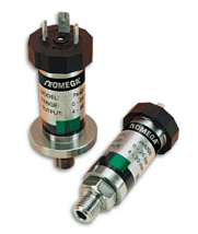
The first set of Sensor and Output fields on the screen represent the Physical Range. This is where the user enters the low and high process values from the sensor. This data can typically be found on the data plate or data sheet of the sensor (typical sensor image, right). The second set of Sensor and Output fields represent the Electrical Output. This is where the user enters the minimum and maximum electrical output values of the sensor, also listed on the data plate or data sheet.
CURRENT LOOP CONNECTION
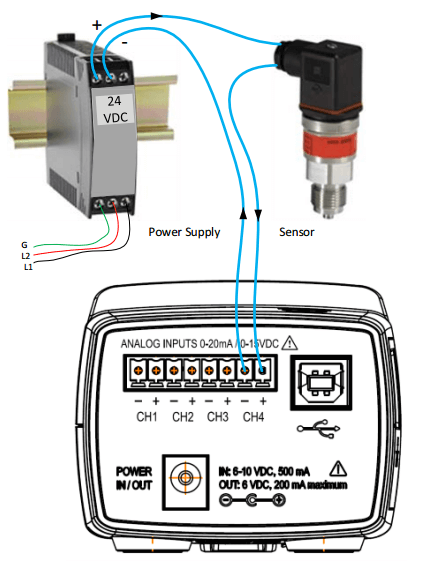
Sensors using current loops are widely used in industry to communicate analog signals in the presence of electromagnetic interference. Both 2- and 3-wire current loops (often referred to as loop powered or separately excited, respectively) are commonly used in industry. Both types of current sensors are illustrated in this section. Internally, the ELITEpro XC uses 0.1% precision 499 ohm resistors to measure the voltage drop impressed by the external current source. Current loop sensors will typically be powered from a 24-volt DC supply. The ELITEpro XC has four measurement channels. The negative terminals of each channel are common to each other and connected to the reference plane for power measurements. For this reason it is imperative that the ELITEpro XC be connected as the last component in the current loop rather than the first if multiple channels are used. Best practices are to use a single power supply for all sensors to reduce the occurrence of ground loop current between supplies.
VOLTAGE CONNECTION

Voltage output sensors and 3-wire current loops will typically use one voltage for powering the sensor and a second voltage (or current) for sending an output signal. Sometimes the power supply ground and signal reference conductor is shared between two circuits resulting in a three wire device. This economy usually comes at the installer’s expense of having to form a junction at the power supply, sensor, or meter. Sensors having four terminals are also popular and are simply connected to the meter by observing the indicated polarity between sensor and meter.
![10-Step Checklist for ElitePro Power Meter Verification [Download Available]](https://www.dentinstruments.com/wp-content/uploads/2022/03/elitepro_installation_with_rocoils-1-500x383.jpg)
