
INTRODUCTION:
Whether this is your first metering project or you’re a seasoned facilities manager, it’s important to remember that a little planning up front can go a long way in making your project easier.
As part of deploying a new power meter, such as the DENT ELITEpro XC, there are several tasks you will need to accomplish to ensure the meter is configured properly for your project. Before leaving the job site, it’s cruical to verify that the meter is installed properly and is recording as expected. After installation, take a few moments to follow the 10 Steps of Meter Verification.
Scroll to the bottom to download a PDF version of this list.
Step 1: Record important information about the installation for future reference.
Keep track of important installation information in one place. Use the list in the downloadable PDF (bottom of post) to jot down important details about each meter that’s installed. Key information to keep track of includes
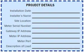
- Installation date,
- Installer’s name
- Site location
- Meter serial number
- Communication setup (IP addresses & port number)
- Description of the load being measured.
Be sure to provide this information to any other personnel who need to access the meter for data downloads.
Step 2: Take photos.

No excuses – everybody has a cell phone in their pocket! Photos are an easy way to remember important details about the installation without having to go back to the project site. If you ever have an issue and need to contact technical support, the photos can make it simple to explain your installation. Take photos of:
- Outside the electrical room to aid in locating the electrical panel for the next person
- Inside the electrical room
- Of the meter installed along with the CT installation and voltage connections
Step 3: Using ELOG software, verify the logger’s Setup Table. Make sure…
- The correct data interval is selected (15 minutes is typical)
- V-high and V-low match the voltage phases the CTs are installed on
- CT type selection matches the CTs used
- CT amp selection matches the CTs used
- CT Phase Shift matches what’s listed in the ELITEpro XC Operator’s Guide
- Recorded values are selected as needed for the project
Step 4: Using ELOG software, verify the logger’s internal clock is set right.
You can verify the logger’s clock by viewing Real-Time Values and synchronizing the time to the PC or manually setting it.
When reading the logger clock or viewing data files, ELOG reads the windows settings and converts the UTC time stamps in the logger to the local time zone of the PC. If the two PCs in different time zones retrieve a data file from the logger, or read the logger clock, they will see different times.
Step 5: Check to make sure all the PhaseChek LEDs are green, which indicates all phase kW are positive and PF > 0.55
- If any LEDs are blue (ELITEpro XC only), the kW will be negative which is most likely caused by the CT being installed backwards.
- If LEDs are red, the PF is less than 0.55, which is most likely caused by the CT being placed on the wrong phase or not matching the Setup Table. It could also be caused by the load’s PF being less than 0.55.
- If the LED flashes red and blue, it indicates that the CT is on backwards and on the wrong voltage phase and not matching what’s listed in the Setup Table
- Note: If using the optional Delta 2-CT connection, it is common for an LED to be red when the system PF is <0.87 and an LED to be blue when the PF is <0.5
Step 6: Using ELOG software, view Real-Time values. Do the numbers make sense?
- Are the load current and watt measurements reasonable for the load?
- Example: If the current reads are 12 Amps for a 100 HP motor, the readings are obviously too low.
- Possible issues could be that the CTs are on the wrong wire, the CT value in the Setup Table is incorrect, or the CT type in the Setup Table is incorrect.
- NOTE: It’s best to choose a CT in which the load will be between 10% and 100% of the CT full scale rating.
- Are the phase currents relatively close to each other (within about 20%) on a load that should be balanced?
- Possible issues might include that the CTs are on the wrong wire, the CT value int he Setup Table is incorrect, or the CT type in the Setup Table is incorrect
- For Wye loads, are the phase watts relatively close to each other (within about 20%)?
- Check for possible problem in phase currents were balanced: The CTs might be placed on the wrong phase, not matching the Setup Table or the CT type in the Setup Table is incorrect.
- Are the phase watts positive?
- If not, it is likely that the CT is installed backwards or the wire connection at the meter is reversed. Check these conditions.
- NOTE: It is possible when using the 2-CT method on a Delta load that one channel/phase can be negative on loads that have poor PF.
- NOTE: Negative values could be correct for co-generation applications such a wind or solar during power generation.
- For WYE loads, are the phase PF readings relatively close to each other when monitoring a balanced load?
- If not, this can be caused by the CT being placed on the wrong phase or not matching the Setup Table
- If available, compare to external references (within a percent or two – no two meters will read exactly the same).
- See if the meter phase voltages match a Digital Volt Meter (DVM)
- Check the meter phase currents with a clamp-on Amp Meter
- Compare the meter phase watts with a clamp-on Power Meter
Step 7: Is the “Logging On” LED flashing green?
If the LED is not flashing, the meter is not recording any data! Make sure the LED is flashing prior to leaving the jobs site.
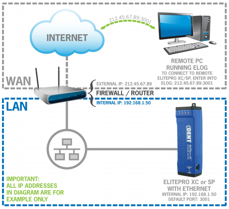
Step 8: If a remote communication method is being used, is the meter communicating?
Wi-Fi troubleshooting:
- Verify the Port Number in the Network Connection window in ELOG matches the meter setting
- The laptop Wi-Fi adapter needs to be in DHCP for use in Access Point mode (DHCP is the default setting)
- The ELITEpro XC IP address in Access Point mode is 192.168.1.1
- If a password is being used in Access Point mode, ensure the correct password is entered. If unsure, re-enter the password using ELOG
- If communication is lost, try:
- Disconnecting the meter from ELOG and reconnecting
- Disconnecting the computer Wi-Fi from the meter’s Wi-Fi
Step 9: Make sure all cabinet doors are closed and locked and all panel screws are tightened
Step 10: Ensure all trash is picked up and the site is left as clean as when you first arrived.
CONCLUSION:
Avoid the common meter installation pitfalls!
We would also love your feedback on this list. What do you do to ensure your meter installation is successful? Comment below with your ideas.
