Using the Analog Channels on the ELITEpro XC to Correlate Your Consumption of Electricity to Environmental, HVAC, or Other Processes

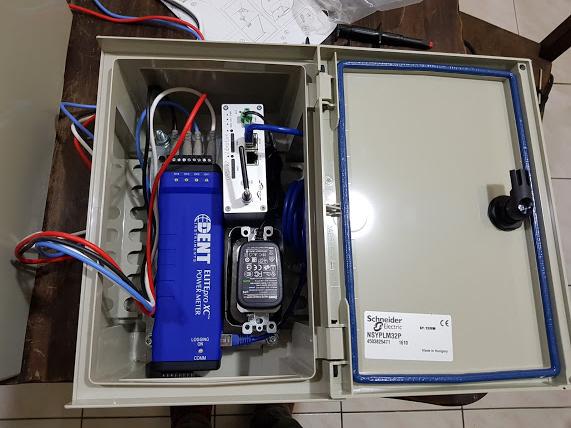
Some features that are often overlooked on the ELITEpro XC Portable Energy Meters are the analog input channels.

Analog inputs are especially helpful when used in conjunction with power measurements to correlate the consumption of electricity with environmental, HVAC plant performance, or other process conditions. Typical uses might include logging ambient temperature, building temperatures, solar insolation, tank pressures, duct flows, etc.

The ELITEpro XC has four analog input channels that can be configured for voltage or current input in any combination among channels. The limiting specifications for anlog input are show in the table below.

Analog Input Technical Specifications
Maximum Input Voltage30 VDC, Unipolar Measurements Only.
Maximum Input Current23 maNote: the current limit will be exceeded before 30 volts of applied potential when selected for current mode or connected with reverse polarity.
A/D16 bit
Input Impedance50.0 K (voltage mode), 499 ohm (current mode)
Sampling Frequency4 HZ – per channel, 16 HZ total throughput
Accuracy<0.2% typical

COMPATIBLE SENSOR TYPES

The following sensor types are supported and selected through the ELOG software interface:

  • 0/4-20 mA externally powered current loop
  • 0-30 VDC single-ended, non-isolated

Note: The ELITEpro XC can measure input voltages up to 30.0 volts. The polarity protection circuitry, however, can only withstand 15 volts of reverse-applied polarity without permanent damage to the meter. The maximum allowable current flowing into the analog input terminal is 23 mA.

CAUTION: Ensure that the sensor current/voltage is within range and the channel is correctly configured using ELOG 15 before connecting external sensors. Sustained exposure to elevated signals may damage the ELITEpro XC and this will void your warranty.
CAUTION: Observe the correct signal polarity when connecting voltage sensors to the ELITEpro XC above 10 volts. Damaging currents may flow from the connected sensor in the event of reverse polarity or misconfiguration and this will void your warranty.

Channel types (voltage or current) should be configured using the ELOG software prior to connecting external sensors. This sequence will prevent the unexpected/unpredictable combinations of voltage transducers connected to low impedance loads (499 ohm) or current transducers with an open circuit.

The first set of Sensor and Output fields on the screen represent the Physical Range. This is where the user enters the low and high process values from the sensor. This data can typically be found on the data plate or data sheet of the sensor (typical sensor image, right). The second set of Sensor and Output fields represent the Electrical Output. This is where the user enters the minimum and maximum electrical output values of the sensor, also listed on the data plate or data sheet.

CURRENT LOOP CONNECTION

Sensors using current loops are widely used in industry to communicate analog signals in the presence of electromagnetic interference. Both 2- and 3-wire current loops (often referred to as loop powered or separately excited, respectively) are commonly used in industry. Both types of current sensors are illustrated in this section. Internally, the ELITEpro XC uses 0.1% precision 499 ohm resistors to measure the voltage drop impressed by the external current source. Current loop sensors will typically be powered from a 24-volt DC supply. The ELITEpro XC has four measurement channels. The negative terminals of each channel are common to each other and connected to the reference plane for power measurements. For this reason it is imperative that the ELITEpro XC be connected as the last component in the current loop rather than the first if multiple channels are used. Best practices are to use a single power supply for all sensors to reduce the occurrence of ground loop current between supplies.

VOLTAGE CONNECTION

Voltage output sensors and 3-wire current loops will typically use one voltage for powering the sensor and a second voltage (or current) for sending an output signal. Sometimes the power supply ground and signal reference conductor is shared between two circuits resulting in a three wire device. This economy usually comes at the installer’s expense of having to form a junction at the power supply, sensor, or meter. Sensors having four terminals are also popular and are simply connected to the meter by observing the indicated polarity between sensor and meter.

Metering Application: Integrating the ELITEpro XC Meter with a Cellular Communication Module for Remote Metering

By Francisco Sotela, Director of Iotech

OBJECTIVE

The objective of this solution is to manage the ELITEpro XC Power Meter from the office without having to perform a site visit to collect the metered data, increasing efficiency and reducing project costs. Learn how the ELITEpro XC was integrated in the ideal remote solution.

DESCRIPTION OF APPLICATION

The power company in Costa Rica has customers throughout the country, many located in remote areas. Often, the power company needs to perform a temporary study (energy audit) with a customer who reports electrical problems, such as excessive consumption or short circuits. The audits are performed using an ELITEpro XC power meter at the customer site.

Because of the distances involved, it was important to develop a remote communication solution for the ELITEpro XC meter. Although the ELITEpro XC can be purchased with a Wi-Fi option, wireless internet is not always available at the customer site. Therefore, it was determined that cellular communications would be required.

Iotech, DENT’s Authorized Distributor in Central America, developed a solution where the ELITEpro XC was integrated with a cellular router in a weatherproof control cabinet. The ELITEpro XC meter was connected to the cellular router via the Ethernet port, allowing the auditors to connect to the ELITEpro XC meter from anywhere in the world using the Internet. Metered values, as well as harmonics, could be viewed in real-time using this solution.

The control cabinet used was weatherproof and could withstand direct sunlight – adding an effective layer of protection to the ELITEpro XC and cellular router. Cables for voltages and current sensors traveled through separate conduits in the side of the cabinet. The cellular communication module was powered by an extension that traveled through the side of the cabinet.

This solution has benefited the power company by saving countless trips into the field to gather data from the energy meters. It has also allowed the engineers in charge of the audit to verify meter setup prior to the installer leaving the field, ensuring proper configuration and reducing the number of field visits.

For more information about this application, please contact Francisco Sotela at Iotech.


Do you have a question about communicating with your ELITEpro XC remotely? If so, contact our technical support department at support@dentinstruments.com.

Save Time + $$$ on Your Next Project: FREE Energy Metering Guide!

As an energy manager, you know one of the fastest ways to start saving on building and equipment costs is to perform an energy audit to identify savings opportunities. Unfortunately, that is sometimes easier said than done. Not only do you need to figure out the right metering equipment for your project, the installation itself can be tricky, too…

Did you know that one of the easiest ways to save money on your next audit was to simply be organized about the installation itself? A little planning can mean the difference between having the correct equipment before the site visit and multiple trips to a site to correct costly installation errors.

Multiple Site Visits = Time and $

For your next metering project, stay organized! The DENT Engineering Team has assembled a step-by-step Metering Project eBook to help you with your next project. Whether you’re facing your first metering project or you’re an experienced auditor, you’re sure to find useful planning information for your future projects. Don’t let important project details slip through the cracks – use the handy checklists in the guide to stay on track. 

Stop Overpaying the Power Company: Energy Audits are Key to Savings

Most companies want to decrease their energy consumption, either for financial reasons, or to be active in reducing their carbon footprint, or both–but some of them aren’t sure where to begin. When the only measure of a facility’s energy usage is the bill customers receive at the end of the month, they may feel their facility is more like the proverbial black hole: power goes in, business happens inside, but it’s not clear exactly how much energy is used where and when. Factory owners may want to know where the heavy usage is inside their plant–how much consumption is used to operate compressors, chillers, pumps, lighting, etc. Office building owners may want to break out the energy consumed in their HVAC vs. lighting systems.

To get an accurate breakdown of energy consumption, a common method is to conduct a short-term energy audit. In an audit, monitoring devices are installed for a period of time to measure all the circuits that are responsible for the overall energy usage of the facility. The resulting data are recorded, demonstrating what areas are consuming the most power. By comparing the consumption of these with industry averages, it’s possible to identify areas where energy can be saved. For example, lighting energy usage that is higher than typical for a business of its size could mean that the facility has unnecessarily high illumination levels or lights in use when not necessary.

When starting an audit, there are many areas of a building that need to be investigated for potential savings. A good building energy audit will indicate how to reduce your energy costs by 10% to 40%, depending on the building. Energy audits typically focus on the following areas within a facility:

  • Lighting Systems
  • HVAC Systems and Controls
  • Compressed Air Systems
  • Renewable Energy Applications
  • Electric Motors and Drives
  • Process Systems
  • Steam Systems
  • Heat Recovery
  • Building Envelope Upgrades

A variety of tools are part of every energy auditor’s toolkit. These items may include an infrared camera, digital pressure and flow gauges, a gas leak detector, a carbon monoxide detector, a combustion analyzer, a moisture meter, and others.

But to determine if there has been a reduction in energy consumption, a recording power meter is also required. For example, the DENT ELITEpro XC, can capture kWh/kW energy and demand data as well as many other relevant energy parameters for diagnostics and monitoring on three-phase or single phase systems. The ELITEpro XC is also ideal for capturing baseline energy consumption before any changes are made to an energy program. This baseline information is crucial in determining the success of any program.

In many cases, a load study can last for a month or more. If a recording power meter is not already part of your toolkit, or if the study is a one-time event, the smart choice may be to rent this equipment instead of purchasing.

DENT Instruments has a network of authorized distributors around the United States, some of which provide equipment rentals. If your next project is short term, give the distributor in your area a call for rental pricing. In addition to the equipment, they are a fantastic resource for advice on how to get started with your measurement project.

HERE ARE THE DENT AUTHORIZED DISTRIBUTORS WHO RENT EQUIPMENT:

        HANOVER TECHNICAL SALESMain Office: Virginia800-304-9043sales@hanovertechnical.comWebsite: http://hanovertechnical.com/
     PANEL COMPONENTS & SYSTEMS (PC&S)Main Office: New Jersey800-523-9194Bill Renshaw (ext 19): bill@pc-s.comRon Aloisio: raloisio@pc-s.comWebsite: http://www.pc-s.com/
 LAKELAND ENGINEERINGOffice Locations: Minneapolis (HQ), Denver, Kansas City, Omaha1-855-544-0321meck@lakelandengineering.comrkucksdorf@lakelandengineering.comWebsite: https://shop.lakelandengineering.com/brands/dent-instruments
 PQ TESTING & RENTALSMain Office: Florida407-421-0846pqtesting@yahoo.comWebsite: http://www.pqtesting.com/