10-Step Checklist for Power Meter Verification [Download Available]

INTRODUCTION:

Whether this is your first metering project or you’re a seasoned facilities manager, it’s important to remember that a little planning up front can go a long way in making your project easier.

As part of deploying a new power meter, such as the DENT ELITEpro XC, there are several tasks you will need to accomplish to ensure the meter is configured properly for your project. Before leaving the job site, it’s cruical to verify that the meter is installed properly and is recording as expected. After installation, take a few moments to follow the 10 Steps of Meter Verification.


Scroll to the bottom to download a PDF version of this list.

Step 1: Record important information about the installation for future reference.

Keep track of important installation information in one place. Use the list in the downloadable PDF (bottom of post) to jot down important details about each meter that’s installed. Key information to keep track of includes

  1. Installation date,
  2. Installer’s name
  3. Site location
  4. Meter serial number
  5. Communication setup (IP addresses & port number)
  6. Description of the load being measured.

Be sure to provide this information to any other personnel who need to access the meter for data downloads.

Step 2: Take photos.

No excuses – everybody has a cell phone in their pocket! Photos are an easy way to remember important details about the installation without having to go back to the project site. If you ever have an issue and need to contact technical support, the photos can make it simple to explain your installation. Take photos of:

  1. Outside the electrical room to aid in locating the electrical panel for the next person
  2. Inside the electrical room
  3. Of the meter installed along with the CT installation and voltage connections

Step 3: Using ELOG software, verify the logger’s Setup Table. Make sure…

  1. The correct data interval is selected (15 minutes is typical)
  2. V-high and V-low match the voltage phases the CTs are installed on
  3. CT type selection matches the CTs used
  4. CT amp selection matches the CTs used
  5. CT Phase Shift matches what’s listed in the ELITEpro XC Operator’s Guide
  6. Recorded values are selected as needed for the project

Step 4: Using ELOG software, verify the logger’s internal clock is set right.

You can verify the logger’s clock by viewing Real-Time Values and synchronizing the time to the PC or manually setting it.

When reading the logger clock or viewing data files, ELOG reads the windows settings and converts the UTC time stamps in the logger to the local time zone of the PC. If the two PCs in different time zones retrieve a data file from the logger, or read the logger clock, they will see different times.

Step 5: Check to make sure all the PhaseChek LEDs are green, which indicates all phase kW are positive and PF > 0.55

  1. If any LEDs are blue (ELITEpro XC only), the kW will be negative which is most likely caused by the CT being installed backwards.
  2. If LEDs are red, the PF is less than 0.55, which is most likely caused by the CT being placed on the wrong phase or not matching the Setup Table. It could also be caused by the load’s PF being less than 0.55.
  3. If the LED flashes red and blue, it indicates that the CT is on backwards and on the wrong voltage phase and not matching what’s listed in the Setup Table
  4. Note: If using the optional Delta 2-CT connection, it is common for an LED to be red when the system PF is <0.87 and an LED to be blue when the PF is <0.5

Step 6: Using ELOG software, view Real-Time values. Do the numbers make sense?

  1. Are the load current and watt measurements reasonable for the load?
    • Example: If the current reads are 12 Amps for a 100 HP motor, the readings are obviously too low.
    • Possible issues could be that the CTs are on the wrong wire, the CT value in the Setup Table is incorrect, or the CT type in the Setup Table is incorrect.
    • NOTE: It’s best to choose a CT in which the load will be between 10% and 100% of the CT full scale rating.
  2. Are the phase currents relatively close to each other (within about 20%) on a load that should be balanced?
    • Possible issues might include that the CTs are on the wrong wire, the CT value int he Setup Table is incorrect, or the CT type in the Setup Table is incorrect
  3. For Wye loads, are the phase watts relatively close to each other (within about 20%)?
    • Check for possible problem in phase currents were balanced: The CTs might be placed on the wrong phase, not matching the Setup Table or the CT type in the Setup Table is incorrect.
  4. Are the phase watts positive?
    • If not, it is likely that the CT is installed backwards or the wire connection at the meter is reversed. Check these conditions.
    • NOTE: It is possible when using the 2-CT method on a Delta load that one channel/phase can be negative on loads that have poor PF.
    • NOTE: Negative values could be correct for co-generation applications such a wind or solar during power generation.
  5. For WYE loads, are the phase PF readings relatively close to each other when monitoring a balanced load?
    • If not, this can be caused by the CT being placed on the wrong phase or not matching the Setup Table
  6. If available, compare to external references (within a percent or two – no two meters will read exactly the same).
    • See if the meter phase voltages match a Digital Volt Meter (DVM)
    • Check the meter phase currents with a clamp-on Amp Meter
    • Compare the meter phase watts with a clamp-on Power Meter

Step 7: Is the “Logging On” LED flashing green?

If the LED is not flashing, the meter is not recording any data! Make sure the LED is flashing prior to leaving the jobs site.

Step 8: If a remote communication method is being used (like Wi-Fi or Bluetooth), is the meter communicating?

Wi-Fi troubleshooting:

  1. Verify the Port Number in the Network Connection window in ELOG matches the meter setting
  2. The laptop Wi-Fi adapter needs to be in DHCP for use in Access Point mode (DHCP is the default setting)
  3. The ELITEpro XC IP address in Access Point mode is 192.168.1.1
  4. If a password is being used in Access Point mode, ensure the correct password is entered. If unsure, re-enter the password using ELOG
  5. If communication is lost, try:
    • Disconnecting the meter from ELOG and reconnecting
    • Disconnecting the computer Wi-Fi from the meter’s Wi-Fi

Step 9: Make sure all cabinet doors are closed and locked and all panel screws are tightened

Step 10: Ensure all trash is picked up and the site is left as clean as when you first arrived.


CONCLUSION:

Avoid the common meter installation pitfalls! Download a copy of this checklist (PDF) to take with you during your next field installation.

We would also love your feedback on this list. What do you do to ensure your meter installation is successful? Comment below with your ideas.

Using the Analog Channels on the ELITEpro XC to Correlate Your Consumption of Electricity to Environmental, HVAC, or Other Processes

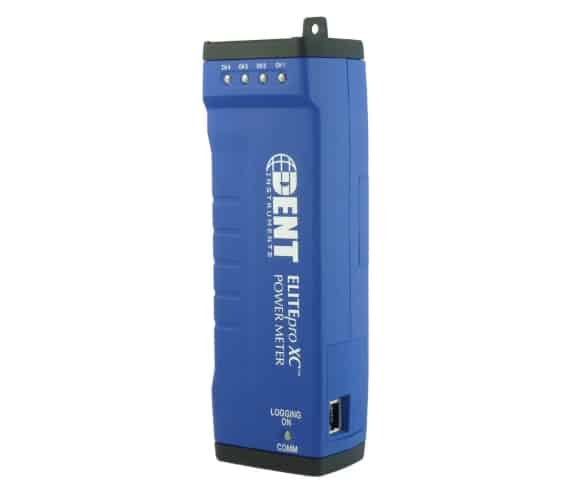
Some features that are often overlooked on the ELITEpro XC Portable Energy Meters are the analog input channels.

Analog inputs are especially helpful when used in conjunction with power measurements to correlate the consumption of electricity with environmental, HVAC plant performance, or other process conditions. Typical uses might include logging ambient temperature, building temperatures, solar insolation, tank pressures, duct flows, etc.

The ELITEpro XC has four analog input channels that can be configured for voltage or current input in any combination among channels. The limiting specifications for anlog input are show in the table below.

Analog Input Technical Specifications
Maximum Input Voltage30 VDC, Unipolar Measurements Only.
Maximum Input Current23 maNote: the current limit will be exceeded before 30 volts of applied potential when selected for current mode or connected with reverse polarity.
A/D16 bit
Input Impedance50.0 K (voltage mode), 499 ohm (current mode)
Sampling Frequency4 HZ – per channel, 16 HZ total throughput
Accuracy<0.2% typical

COMPATIBLE SENSOR TYPES

The following sensor types are supported and selected through the ELOG software interface:

  • 0/4-20 mA externally powered current loop
  • 0-30 VDC single-ended, non-isolated

Note: The ELITEpro XC can measure input voltages up to 30.0 volts. The polarity protection circuitry, however, can only withstand 15 volts of reverse-applied polarity without permanent damage to the meter. The maximum allowable current flowing into the analog input terminal is 23 mA.

CAUTION: Ensure that the sensor current/voltage is within range and the channel is correctly configured using ELOG 15 before connecting external sensors. Sustained exposure to elevated signals may damage the ELITEpro XC and this will void your warranty.
CAUTION: Observe the correct signal polarity when connecting voltage sensors to the ELITEpro XC above 10 volts. Damaging currents may flow from the connected sensor in the event of reverse polarity or misconfiguration and this will void your warranty.

Channel types (voltage or current) should be configured using the ELOG software prior to connecting external sensors. This sequence will prevent the unexpected/unpredictable combinations of voltage transducers connected to low impedance loads (499 ohm) or current transducers with an open circuit.

The first set of Sensor and Output fields on the screen represent the Physical Range. This is where the user enters the low and high process values from the sensor. This data can typically be found on the data plate or data sheet of the sensor (typical sensor image, right). The second set of Sensor and Output fields represent the Electrical Output. This is where the user enters the minimum and maximum electrical output values of the sensor, also listed on the data plate or data sheet.

CURRENT LOOP CONNECTION

Sensors using current loops are widely used in industry to communicate analog signals in the presence of electromagnetic interference. Both 2- and 3-wire current loops (often referred to as loop powered or separately excited, respectively) are commonly used in industry. Both types of current sensors are illustrated in this section. Internally, the ELITEpro XC uses 0.1% precision 499 ohm resistors to measure the voltage drop impressed by the external current source. Current loop sensors will typically be powered from a 24-volt DC supply. The ELITEpro XC has four measurement channels. The negative terminals of each channel are common to each other and connected to the reference plane for power measurements. For this reason it is imperative that the ELITEpro XC be connected as the last component in the current loop rather than the first if multiple channels are used. Best practices are to use a single power supply for all sensors to reduce the occurrence of ground loop current between supplies.

VOLTAGE CONNECTION

Voltage output sensors and 3-wire current loops will typically use one voltage for powering the sensor and a second voltage (or current) for sending an output signal. Sometimes the power supply ground and signal reference conductor is shared between two circuits resulting in a three wire device. This economy usually comes at the installer’s expense of having to form a junction at the power supply, sensor, or meter. Sensors having four terminals are also popular and are simply connected to the meter by observing the indicated polarity between sensor and meter.

Connect to a Remote ELITEpro XC Using Port Forwarding

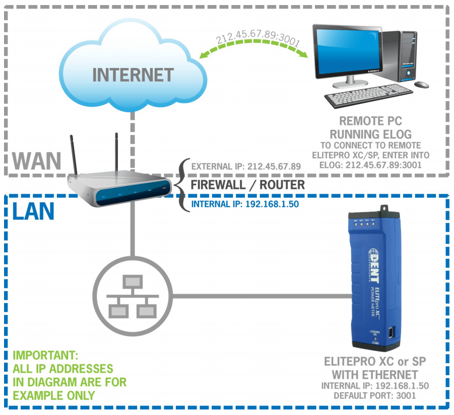
What happens if your ELITEpro XC Portable Electric Data Logger is on a local area network at a remote project site, but you’re hundreds of miles away, at your office, and need to download data off the meter? Port Forwarding makes it possible to complete the download. And, with a little planning, you probably already have everything you need to successfully download your data.

Port forwarding is a name given to the combined technique of:

  1. Translating the address and/or port number of a packet to a new destination
  2. Possibly accepting such packets in a packet filter (firewall)
  3. Forwarding the packet according to the routing table

Port forwarding allows remote computers (for example, computers on the Internet) to connect to a specific computer or service within a private local area network (LAN). In the case of the ELITEpro XC  (or ELITEpro SP) with Ethernet, port forwarding allows remote connection between the ELITEpro XC and a computer on another network through the firewall via ELOG software.

For instance, if the ELITEpro XC is on the local area network at a remote project site, but you wish to download data off the meter from the office, you can remotely access the ELITEpro XC from any computer with an Internet connection through ELOG.

REQUIREMENTS

Prior to beginning, confirm the following information:

  1. Know the external IP address of the router on the network with the ELITEpro XC. This address is usually assigned by the ISP and is typically static. However, it may be dynamic, changing the address every other day. This can be easily found by someone inside the network by visiting www.whatsmyip.com.
  2. Confirm that your router can be configured for port forwarding. Verify this with your router’s documentation or by visiting the manufacturer’s website.
  3. Know the ELITEpro XC meter’s IP address.
Note: The ELITEpro XC itself does not need to be configured for Port Forwarding. All the configuration takes place on the router.

Each router manufacturer uses slightly different software. Check your router’s documentation for specific directions on how to port forward with your router’s software. Regardless of what software is on your router, you’ll be required to enter the same general information.

  1. A text field where you can type the name of the application or service (in this case, it’s helpful to reference the “ELITEpro XC” or the EXC’s serial number).
  2. Incoming port the router should watch for.
  3. The protocol to watch for: TCP or UDP. Choose “both” if you’re unsure.
  4. The IP address that is the destination for this port’s request (i.e., the EXC’s IP address).
  5. Which port the request should be targeted to on the destination IP. The default is 3001.

INSTRUCTIONS

Here are the steps to connecting your networked ELITEpro XC from a different network:

  1. Obtain an internal IP address that is routable to an external IP address. If you are unsure of which IP address to use, check with your IT department.
  2. The external IP address gets forwarded to the internal IP address. For instance, the external IP address 212.45.67.89 may be forwarded to internal IP address 192.168.1.50.
  3. Determine which port should e used to connect to the ELITEpro XC. The default port is 3001. Check with your IT department if you are unsure.
  4. Using ELOG on the remote PC, go through the menu: Logger > Communication > Network Connect.
  5. Enter the external IP address for the network you wish to connect to in the Network IP address box.
  6. Enter the Port Number for the logger you wish to connect to.
  7. Click OK.
  8. You should now be connected to the remote ELITEpro XC.

FOR MORE INFORMATION

You may download a PDF copy of this document to take with you into the field here.

If you need technical assistance with your ELITEpro or ELOG software, contact DENT Tech Support.

Easy Steps to Choosing the Right Current Transformer

There’s nothing more frustrating than arriving at the project site to complete a meter installation only to realize you do not have the right current transformer in your toolkit. Not having the right tools for any job is a waste of both time and money. To avoid this, a little pre-planning goes a long way. 

Current transformers are available in a variety of styles, sizes, and amperage ranges. They vary in output and accuracy as well. With so many variables, it is sometimes difficult to choose exactly the right CT for a project. Or is it?

Whether you need assistance with choosing the right CT, or have a related inquiry, contact us at DENT Instruments.

Answer the Following Questions to Find the Right Current Transformer

Selecting the right current transformer can be as easy as answering a few questions about your project, the site, and the goals. You may be able to answer some of these questions before even setting foot on your project site. Others, such as knowing whether there is a space constraint in your electrical panel, are best answered after a site visit. Answer a few questions up front to save major headaches down the road.

QUESTION 1: WHAT TYPE OF POWER METER ARE YOU USING?

One thing to keep in mind is that just because a current transformer is compatible with a meter does not mean that it’s the best choice. For example, did you know that all DENT CTs are compatible with both ELITEpro and PowerScout series instruments? Even though they work together, a clamp-on CT isn’t the best choice to use with a PowerScout. Why? Because part of the appeal of a clamp-on CT in the first place is that it’s easy and convenient to move between panels. In fact, you’re paying more for that extra convenience. The PowerScout, along with other submeters in the industry, are designed to be permanently installed so why pay for the convenience of a clamp-on when you’re not moving it anyway?

Some ways meter choice impacts CT choice:

  1. CT inputs- is your meter designed for mV output CTs or amp output? Common industry standards are 333mV, 1A, or 5A. DENT meters are compatible with 333mV.
  2. Will the meter be installed permanently (such as with a PowerScout or other submeter) or will you be moving the meter from location to location (such as with energy audits)?
  3. Does the meter have the ability to work with flexible Rogowski coils either by themselves or with an amplifier/integrator?

QUESTION 2: HOW MANY AMPS DO YOU PLAN ON MEASURING?

Perhaps one of the most important questions to answer is how many amps will be measured. You will typically know this ahead of a site visit because it’s typically dictated by your project goals. If your goal is to measuring a lighting load in a small office, the CT required will be much smaller than if you plan on measuring a full building load for a large complex.

Keep in mind that best CT performance occurs when the current flow is between 10% and 100% of the CT full-scale value. For example, let’s say you wanted to measure four lighting circuits with #12 wires and 20A breakers. When the lights are on, the amperage measures 45 amps. The ideal CT for this example is a 50A split core current transformer.

But what about a Rogowski coil? They are easy to install and work over a broad range. Keep in mind that the best CT accuracy occurs when the load operates as close to the full rating of the CT as possible. If the load is under 20A, generally speaking a Rogowski coil is not the right choice because it is simply too big for that load. In addition, current values below 5A may cause the meter to read 0 amps.

What happens if you move your meter between many different loads? Sometimes the best solution in this case is to keep two different sets of CTs in your toolkit – one set for small loads (for example, a set of 50A split cores) and one set for larger loads, like Rogowski coils. This way, you’re covered for many different environments.

QUESTION 3: DO YOU REQUIRE A REVENUE-GRADE CT?

Thinking about your project type and goals, it’s important to keep in mind what the end-data will be used for. If you’re doing a measurement and verification (M&V) project, a standard accuracy (1% accuracy) may be accurate enough to achieve your project goals. If you are using a revenue grade meter for tenant submetering or billing purposes, every bit of accuracy counts – and a revenue grade CT would be ideal.

Examples for when to use a Standard Accuracy CT:

  1. Load studies
  2. Measurement & Verification applications

Examples for when to use a Revenue-Grade CT:

  1. Demand Metering
  2. Tenant Submetering
  3. Tenant Billing
  4. Your meter is also revenue grade

QUESTION 4: HOW LONG WILL YOUR PROJECT LAST?

Some CTs are easier to install and move around than others. Available CT styles generally include:

  • Split Core – removable leg or hinge design
  • Clamp-On – clothes-pin design, one handed operation
  • Rogowski Coil – flexible “rope-style” CT
  • Solid Core – rigid; conductor must be inserted through window

Split core, clamp-on, and Rogowski coil CTs are designed to be installed without disconnecting any wires. With the solid core, you must disconnect the conductor to feed it through the window opening of the CT. This can be an inconvenience under certain circumstances and probably not handy if you plan on moving the meter around often.

No matter which type of CT you choose, if possible, always de-energize the circuit to be monitored and follow full safety precautions outlined in your equipment manuals.

QUESTIONS 5 & 6: HOW MUCH “FREE” SPACE DO YOU HAVE IN THE PANEL? HOW BIG IS THE CONDUCTOR TO BE MEASURED?

Space constraints can be a real problem in most electrical panels. It’s possible that your meter is not the only piece of monitoring equipment installed. When multiple meters and CTs are already crammed in, extra small or flexible CTs become even more attractive. (Note: NEC does not allow equipment to exceed 75% of the electrical panel space.)

Also important to consider: What is the size of the conductor that you’ll be measuring? Is it 20 gauge wire or are you measuring around a buss bar? A split core may be ideal for a small wire, but there’s no chance that will work around a buss bar. Generally speaking, CTs with larger window openings also are designed to measure higher amps.

NEED HELP SELECTING A CT FOR YOUR PROJECT?

If you’ve read through these questions and are still unsure of which CT is best, remember that we are here to help! Contact DENT Instruments to discuss your project requirements. We will help you select equipment tailored to your project needs.

How to Update the Firmware on the ELITEpro XC Power Meter

Firmware is software that is used as the control program for the microprocessor in your ELITEpro XC power meter. Firmware updates provide new features and bug fixes for the meter and can be field-installed on the ELITEpro XC (as opposed to needing to come back to the factory for an upgrade). Here’s how you can make sure your firmware is update-to-date & perform an update if needed.

New firmware files are generally bundled with updated ELOG software. Recent versions of ELOG check for software updates automatically. New software and firmware can be downloaded at no charge from the DENT website on the Software Download Page.

You can check the firmware version of your ELITEpro XC from the Tools menu in ELOG software. Select Tools > Update Logger Firmware. The Firmware Update dialog box displays. No update is required if your Firmware File version and the Logger Version are the same.


DOWNLOADING AND INSTALLING FIRMWARE

To install firmware updates, first make sure that your logger is connected via USB cable. Then:

Step 1: Select Tools > Update Logger Firmware.

The following dialog box displays:

Step 2: If necessary, click the Browse button to locate the firmware update file.

Step 3: Click Update

Step 4: The Update Progress bar displays the progress of the firmware update.


If you’re having trouble updating the firmware for your logger, please contact DENT Tech Support for assistance.

Measuring DC Loads with an ELITEpro XC

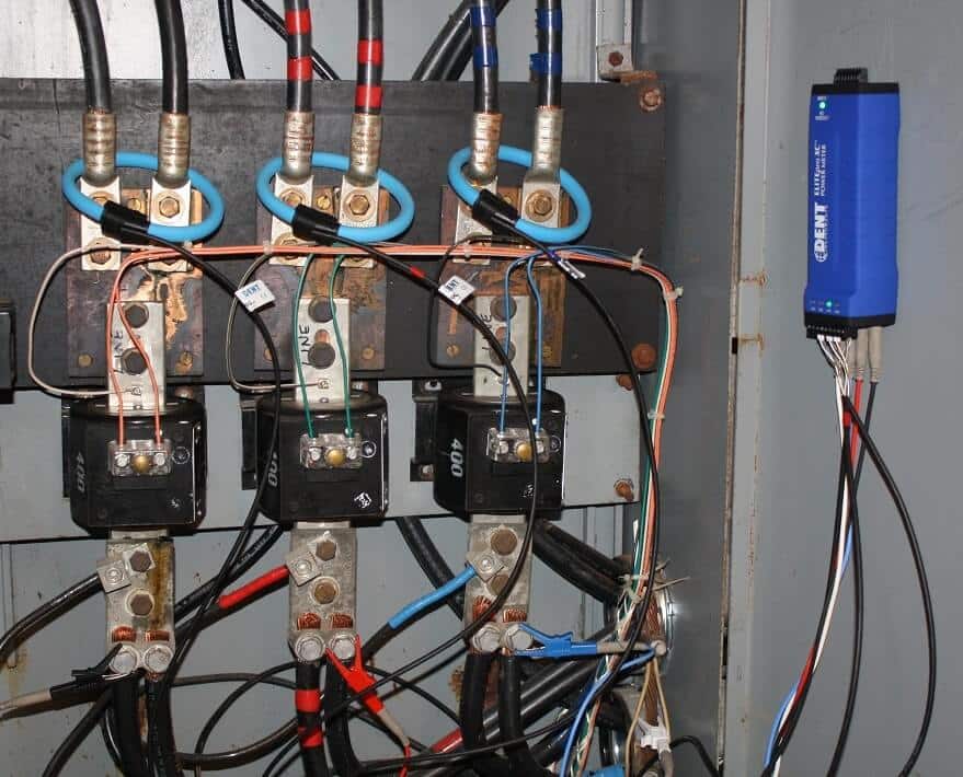
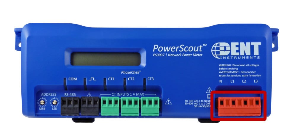
The ELITEpro XC current input channels can accept +/-1VDC. The ELITEpro XC Portable Power Data Loggers analog channels can accept any sensor that has a 0-10 V or 0-20 mA or 4-20 mA signal. What does this mean for DC measurements? Non-DENT sensors may be used on the current and/or analog inputs to measure DC loads. Note that when the DC transducer is connected to the ELITEpro XC CT input, DC power will be reported as long as the DC voltage is connected to the voltage inputs. When the DC transducer is connected to the analog inputs, DC power will not be reported.

Below are two options for measuring DC loads with an ELITEpro XC instrument.


USING THE AEMC MR521 AC/DC CURRENT PROBE

The AEMC MR521 can be used either on the CT inputs or the analog inputs.

USING THE MR521 ON THE CT INPUTS

When using the AEMC MR521 on the ELITEpro XC CT inputs, you may select from two amperage ranges: 100A or 1000A.

  1. 150A:10 mV/A range = 100 Amps DC max
  2. 1500:1 mV/A range = 1000 Amps DC Max

USING THE MR521 ON THE ANALOG INPUTS

If the CT is used on the analog inputs, the full 150A or 1500A range can be used.

OTHER INFORMATION

Note that the AEMC MR521 has a 50 hour battery life and a 2-5% accuracy. List price is $389 (cannot be ordered from DENT). Also keep in mind that a minimum of 80VDC is needed to power the ELITEpro XC.


USING THE NK TECHNOLOGIES DT SERIES DC CURRENT TRANSDUCERS

The NK DT Series current transducers can be used on DC currents from 0-50A or 0-100A depending on the NK DT model chosen. The NK DT Series have 3 available output ranges that must be chosen at the time of purchase.

USING THE NK DT ON THE CT INPUTS

If you wish to use the NK DT on the ELITEpro XC CT inputs, select an NK DT model with 333mV out.

USING THE NK DTON THE ANALOG INPUTS

If you wish to use the NK DT on the ELITEpro XC analog inputs, select an NK DT model with 10VDC output.

POWER SUPPLY OPTIONS

The NK DT Series current transducer has two power supply options. If you plan on using the CT with the ELITEpro XC’s CT input channels and power the NK DT transducer via the ELITEpro XC’s 6VDC power out, choose the 5VDC power supply option. Cannot be ordered from DENT.


FOR MORE INFORMATION

For questions outside the scope of this document, please contact DENT Technical Support at: support@dentinstruments.com / 541-388-4774.

Migration Guide: Switching from the PowerScout to PowerScout HD Series Meters

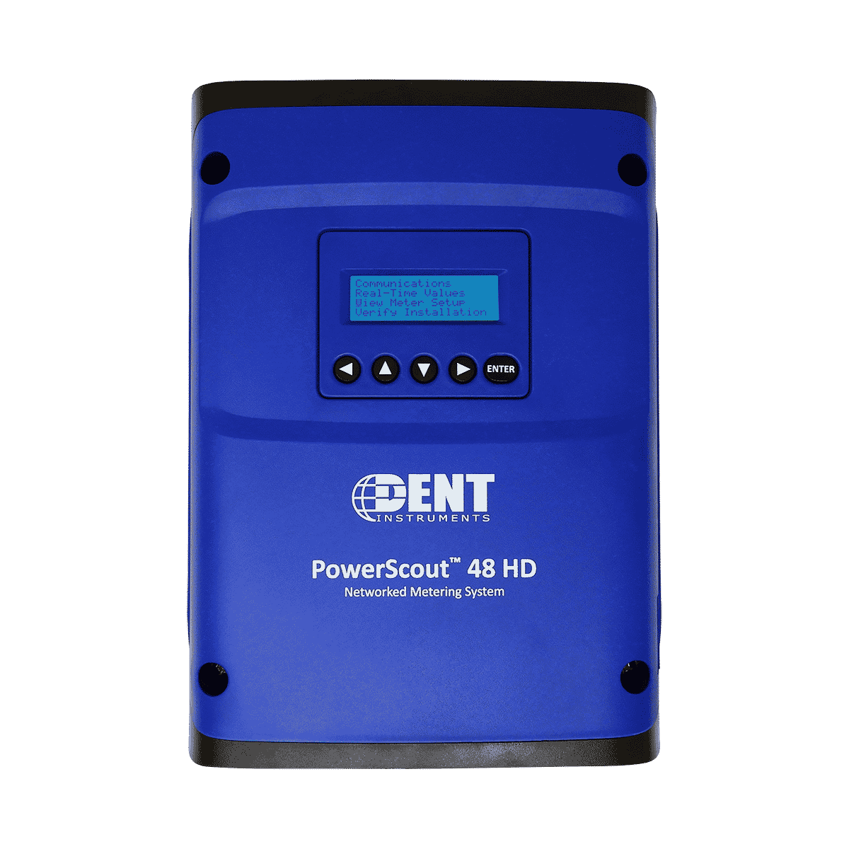
Are you an existing PowerScout user who is looking up add the PowerScout 12 or 48 HD to your toolkit? Or, maybe you’re swapping out a PowerScout 3037 and upgrading to a multi-channel PowerScout 48 HD? Before you do, you should note that there are important differences between the PowerScout and PowerScout HD Series meters. Don’t worry – we’re here to help! We’ve put together some helpful information to help you migrate from first/second generation PowerScout meters (PowerScout 3, 3+, 3037, 18, and 24) to the PowerScout HD Series (PowerScout 12 HD and PowerScout 48 HD).

Below, you will find a series of tables that breakdown the differences between the two meter types. You’ll see right away that there are differences in installation, communications, programming, and registers. These differences are important to keep in mind during meter selection and configuration.

But first, here’s a little more information on the main differences. Full information can be found in our PowerScout to PowerScout Migration Guide.

  • The Modbus register and BACnet Objects schemes are different between the PowerScout 3037/24 and PSHD meters. The PSHD meters now report all data in floating point format which requires less manipulation (such as scaling) by the host RTU. Register organization has been improved by adopting the SunSpec three phase net metering model as a basis.
  • The Windows® configuration utility “ViewPoint HD” is not compatible with PowerScout 3037/24 and can only be used with PSHD meters. PowerScout 3037/24 devices must continue to use legacy ViewPoint 4 software.
  • New capabilities. The PowerScout HD Series has expanded upon the feature set of the PowerScout series by adding Alarms, Interval Data Recording, and Pulse Inputs. Along with new features comes new analytics such as THD, Theta, and installation diagnostics.
METER CONFIGURATION DIFFERENCES
METER INSTALLATION DIFFERENCES
VERIFICATION & COMMUNICATION DIFFERENCES
RTU PROGRAMMING & SCRIPTING DIFFERENCES
RESOURCES

Please review all documentation prior to working with or installing the PowerScout HD. For technical support, please contact us.

Optimizing Performance from Rogowski Coil Current Transformers

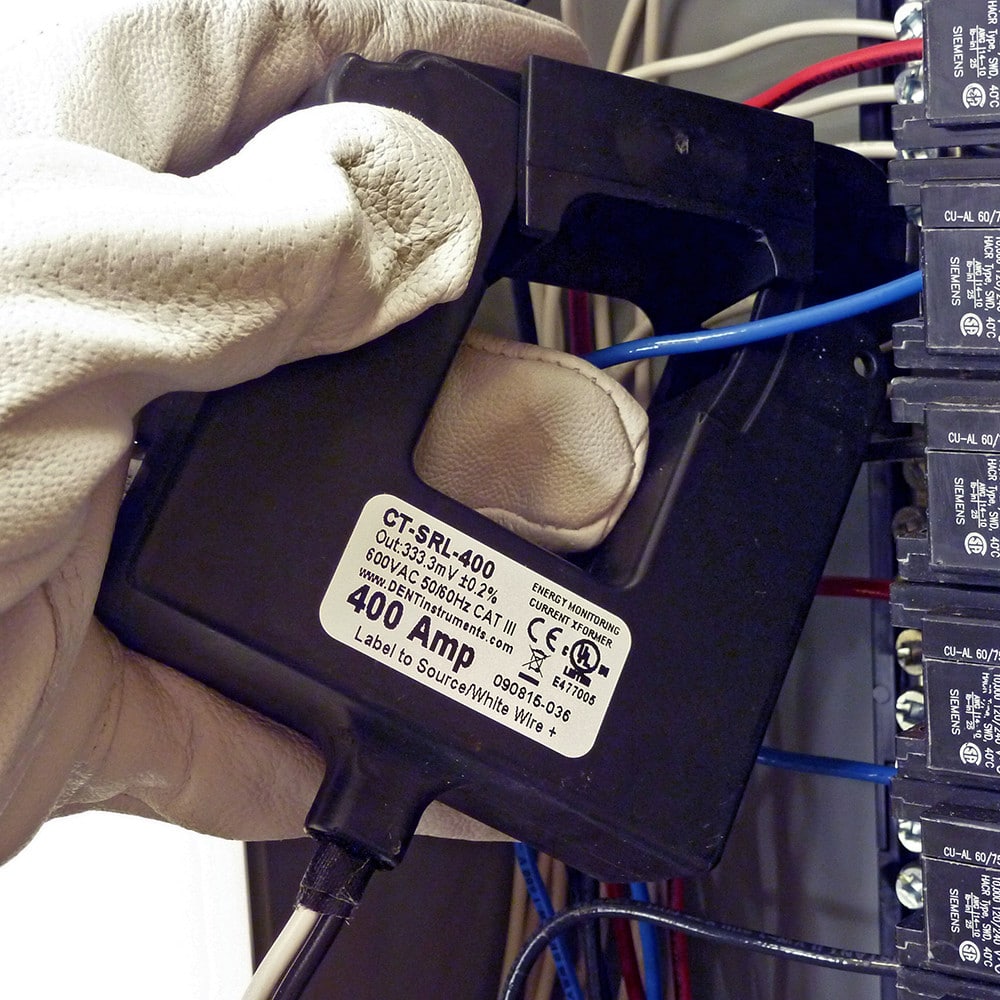
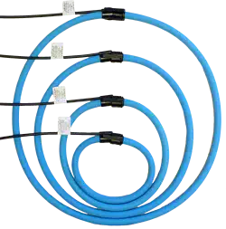
WHAT IS A ROGOWSKI COIL?

A Rogowski coil, named after Walter Rogowski, is an electrical device for measuring alternating current (AC) or high-speed current pulses. It consists of a helical coil of wire with the lead from one end returning through the center of the coil to the other end so that both terminals are at the same end of the coil. The whole assembly is then wrapped around the straight conductor whose current is to be measured.

Since the voltage that is induced in the coil is proportional to the rate of change of current in the straight conductor the output of the Rogowski coil is usually connected to an electrical (or electronic) integrator circuit in order to provide an output signal that is proportional to the current.

The relationship between voltage and rate of change of current is explained in the following equation where V is voltage and M is a constant:

WHY CHOOSE A ROGOWSKI COIL CURRENT TRANSFORMER?

Flexible Rogowski Coils, such as the DENT RoCoil, are designed for easy placement around cable bundles, large busbars, or within tight breaker panels. Their design has several advantages over traditional split core current transformers including:

  1. Open-ended, flexible design allows it to be wrapped around a live conductor without disturbing it.
  2. Rogowksi coils feature an air core rather than an iron core, which results in low inductance and faster response time to changing currents.
  3. Highly linear, even when subjected to large currents such as those used in electric power transmission, welding, or pulsed power applications.
  4. Largely immune to electromagnetic interference.

HOW TO MAXIMIZE PERFORMANCE FROM A ROGOWSKI COIL CURRENT TRANSFORMER

Rogowski coil accuracy is usually calibrated with the conductor centered in the CT window. In practice, however, the CT typically hangs on the conductor which can introduce measurement errors. Note that the error is greatest when the CT connector hangs on the conductor. The following diagram is an example of the type of error that could be introduced simply by moving the conductor to different positions within the opening of the Rogowski coil.

Best practice for Rogowski coil installation is to center the conductor as best as conditions allow. In addition, it’s a good idea to keep any other conductors (those you do not wish to measure) as far away from the Rogowski coil as is practical.

Also, keep in mind that although a Rogowski coil is ideal for large amperage loads, accuracy of the coil may be reduced on smaller loads (<20A). Additionally, the meter you are using may “snap to zero” if the loads is under a certain threshold. This may result in recording “0” during times when a small load is actually present (such as during after hours or weekends in a facility when most loads are shut off). Check with DENT Instruments for current transformer recommendations on your specific project – we would be happy to provide advice on choosing the right sensor.

For more information on DENT RoCoil current transformers, see the RoCoil page here:

Need a quote for current transformers or power meters? Contact us today!

PowerScout 3037 to PowerScout 3 HD Migration Guide

This guide defines key differences between the PowerScout 3037 and the updated PowerScout 3 HD meters. It is intended for current PowerScout 3037 users who are either replacing a PowerScout 3037 with a PowerScout 3 HD or working in an environment with both meter types.

For questions outside the scope of this guide, please refer to the PowerScout HD Manual or contact us.

DENT Instruments has responded to the growing needs of the energy and building automation control markets by introducing the PowerScout HD (PSHD) series of networked power meters.

The HD moniker reflects a “High Definition” design by bringing more points into a single meter and increasing data fidelity. While the original PowerScout series and the new PSHD series share many of the same popular features such as: being self-powered from line voltage, multi-protocol in all models, and ease of configuration, there are some important distinctions of which integrators and end-users need to be aware.

Main Differences: PowerScout 3037 vs. PowerScout HD

  1. The Modbus register and BACnet Objects schemes are different between the PowerScout 3037 and PowerScout 3 HD meters. The PS3HD meters report all data in floating point format which requires less manipulation (such as scaling) by the host RTU.Register organization has been improved by adopting the SunSpec three phase net metering model as a basis. The PS3HD register/object list is shared by all PowerScout HD meter models and is available as an Excel® document.The PowerScout 3037 and PSHD register space is non-overlapping so that both meter types can exist within the same network allowing for expansion with minimal disruption of existing scripts and programs.BACnet object types in PSHD have been updated to include all the Standard Objects in BACnet version 135-2016 including organization of elements through Structured View.
  2. The Windows® configuration utility “ViewPoint HD” is not compatible with PowerScout 3037 and can only be used with PSHD meters. PowerScout 3037 devices must continue to use legacy ViewPoint 4 software.PSHD meters can utilize updated ViewPoint HD software, which includes new analysis and troubleshooting features such as waveform capture, phasor plotting, and harmonic analysis. The PSHD meter can also be configured via a smartphone or tablet via the meter’s built in web server.
  3. New capabilities: The PowerScout HD Series has expanded upon the feature set of the PowerScout series by adding Alarms, Interval Data Recording, and Pulse Inputs. Along with new features comes new analytics such as THD, Theta, and installation diagnostics.

We have highlighted major differences between the product lines in a series of tables on the following pages. Please review this document, along with the PowerScout HD Manual, prior to working with or installing the meter.

Resources

Please review all documentation prior to working with or installing the PowerScout HD. For technical support, please contact us at support@dentinstruments.com.

PowerScout HD Manual

PowerScout HD Register List (Excel®)

Selecting a Power Meter: Find the Right Tool for the Job

“I need a meter.”

This is where the majority of customer conversations begin at DENT. When you learn that your project includes metering or logging energy consumption, it’s clear that you’ll need some piece of equipment to make that happen. Here’s a list of questions to help you decide which DENT meter is the right one.

QUESTION 1: HOW LONG WILL YOUR PROJECT LAST?

Is your project a 30-day load study or will you permanently be installing a meter within your building? The answer to this first question often dictates which meter is best for you.

If your answer is a 30-day load study, an energy audit, or a measurement and verification (M&V) project, the ELITEpro XC is a solid choice. The ELITEpro XC is portable and can be easily moved between panels or to a new location at the end of one project. This is why it’s often the best choice for a temporary study.

On the other hand, if you plan on permanently installing a meter for building submetering, tenant submetering, or demand response, the PowerScout 3037 or PowerScout 24 will be more suitable. The PowerScout is hard-wired into the panel (as opposed to connecting with croc or alligator clips), making it less portable than the ELITEpro.

QUESTION 2: HOW DO YOU WANT TO COLLECT THE DATA?

The ELITEpro and PowerScout instruments handle data collection in two different ways. How data is collected will likely have a large impact on which meter you decide to use.

The ELITEpro has 16 MB of on-board, non-volatile memory for data storage. Data is recorded as the metering session continues and, once the session is complete, the user can download the data from the meter using a USB cable, over Ethernet, or Wi-Fi (depending on meter configuration). Data is downloaded from the meter using a program called ELOG. Once downloaded, the data can be analyzed using ELOG or can be exported to Excel.

If you prefer walking up to the logger, connecting a laptop, and downloading your data, then the ELITEpro is the right choice.

By comparison, the PowerScout does not have any on-board memory for data collection. Instead, data is sent from the meter via Modbus or BACnet communications to a separate data logger or building automation and controls system. The PowerScout can use either BACnet IP or MS/TP protocol or Modbus TCP or RS-485 protocol for sending commands or retrieving data.

If your preference is to interface with the meter through your building automation system or via a remote dashboard display, the PowerScout is right for you.

QUESTION 3: HOW MANY PHASES DO YOU NEED TO MEASURE SIMULTANEOUSLY?

Are you measuring single or three-phase loads? How many of each do you wish to monitor simultaneously?

With the ELITEpro or PowerScout 3037, you can measure single phase loads or one three phase load. The PowerScout 24 allows for up to 24 single phase or 8 three-phase or a combination of single and three-phase using any mix of CTs.

If you require on-board memory (ELITEpro), but need to measure more than one three-phase load at a time, using multiple ELITEpros may be your best option.

QUESTION 4: DO YOU REQUIRE REVENUE GRADE ACCURACY?

The PowerScout 3037 is a revenue grade meter with accuracy of 0.2% or better (ANSI C12.20-2010 qualified Class 0.2). The PowerScout 24 is revenue grade with accuracy of 0.5% or better (ANSI C12.20-2010 Class 0.5).

The ELITEpro accuracy is better than 1%, which is ideal for energy audits, load studies, and M&V work.

QUESTION 5: WHY CAN’T I JUST USE A SMARTLOGGER INSTEAD OF AN ELITEPRO OR POWERSCOUT?

Actually…you can, under certain circumstances. But it’s important to understand what the SMARTloggers were designed for and their limitations.

SMARTloggers are time-of-use loggers. They are designed to give you run-time information for a load. There are four different “flavors” of SMARTlogger:

  • CTlogger: Has an external CT for using on energy-consuming devices with a power cord
  • LIGHTINGlogger: Has an internal photo-sensor for measuring on-time of lights
  • MAGlogger: Measures on-time for motors (or anything generating a magnetic field)
  • CONTACTlogger: Has dry contacts for monitoring closures (such as with a door or switch)

Take the LIGHTINGlogger, for example. If you have the LIGHTINGlogger installed in your light fixture, it’s going to sense when the lights turn on and off. It will record that information with a time and date stamp. Once you download the data from the logger using SMARTware, you will see the on/off transitions for the light. Maybe your light was turned on at 12:38 AM and turned off at 12:58 AM. It’s easy to see exactly how long your light was on. Here’s a sample of the data output:

All SMARTloggers work in the same manner, but are designed to monitor other types of loads, as outlined above.

What happens when you want to know how much energy your light was consuming. The logger itself doesn’t tell you this information without doing some post-processing. You can set the connected load’s kW in SMARTware software to make an estimate on energy consumption.

This is the real difference between the SMARTloggers and a true power meter, such as the ELITEpro or PowerScout: The SMARTloggers will only be able to give you an estimate on energy usage based on the time a load is on multiplied by how many kW you input in the software. If your question is, “How long has my pump been running?” and not “How much energy is my pump consuming?” then the SMARTlogger is an excellent choice.

QUESTION 6: I’M STILL NOT SURE WHICH METER TO CHOOSE. HELP!

Give DENT Instruments a call and we will help you find a solution for your project. Also, be sure to download our  FREE Metering Project eBook for time & money-saving tips for your next project. The eBook also features multiple checklists to keep you project on track.